Near-field goniophotometry supports the development of energy efficient luminaires and solid state lighting
The measurement of luminaires has traditionally been performed with a photometer placed in the far-field, which measures the illuminance from the light source one angle at a time. A near-field goniophotometer exploits the latest advances in imaging photometry and represents a more affordable and flexible option compared with a far-field instrument.
For many years, light fittings or luminaires have been measured using a photometer placed in the photometric far-field, which records the illuminance (in lux) from the light source for one angle of azimuth and elevation at a time. The device under test is mounted on a motorised goniometer stage and the photometer measures luminous intensity as a function of angle. This paper describes a near-field goniophotometer, which exploits the latest advances in imaging photometry - the illuminance meter is replaced by an imaging photometer that records luminance as a function of angle. Near-field luminance images are then ray-traced to generate far-field luminous intensity values and standard photometric data. Near-field luminaire measurements are more affordable both in terms of their capital cost as well as much reduced space requirements compared with far-field instruments. Near-field data means that source illuminance can be computed at any distance from the luminaire.
Standard Photometric Data
Lighting designers need to know the number and positioning of luminaires (light fittings) required in a room to achieve the desired light level. The luminaire manufacturer is therefore required to provide light output data that defines the light level that the fitting will produce in a given direction and at a specified distance. To aid with the modelling of lighting schemes, designers rely upon lighting design software, the most popular of which are DIALux (http://www.dialux.com/) and Relux (http://www.reluz.biz/). Modelling software requires that the light output from the luminaire is presented in a defined format, commonly referred to as standard 'photometric data'. There are two file formats in common use – EULUMDAT (.ldt) and IESNA (.ies).
Let's consider how we specify the 'brightness' of a light source. Luminous flux is the total light emitted from a source and is specified in units of lumens (lm). Luminous intensity is that property of a light source, which describes the luminous flux emitted per unit solid angle in a given direction. It is used to describe the output of a light source in the photometric far-field. Luminous intensity is expressed in units of lumens per steradian or candelas (cd). Conversely, the equivalent near-field property is luminance, being the flux emitted per unit solid angle per unit area in a specified direction. Luminance is given in units of lumens per steradian per square meter or candelas per square meter (cd/m2). The illuminance received at a surface is expressed in units of lumens per square meter, or lux (lx). In the photometric far-field, the illuminance from a light source varies with the inverse square of the distance travelled.
Both EULUMDAT and IES standard photometric data files comprise values of luminous intensity from the luminaire as a function of angle, formatted in standardised formats for use in lighting design software. The instrument typically used to generate standard photometric data is a light meter (or photometer) and a means of rotating and tilting the fitting to the chosen angles (the goniometer). Together, the apparatus is called a goniophotometer.
Far-Field Photometric Measurements
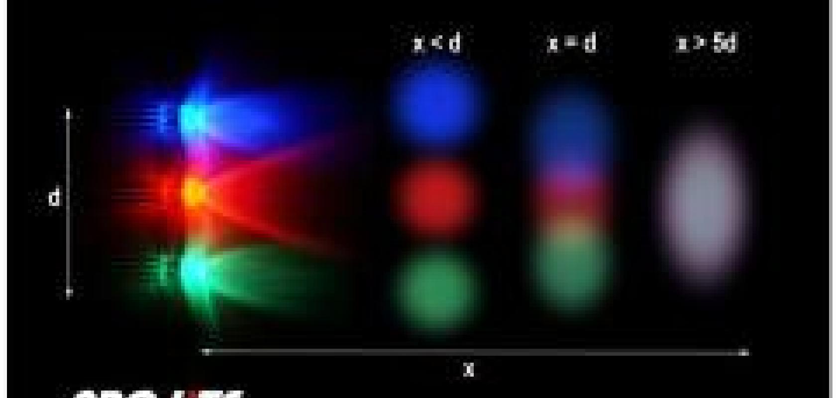
The concept of 'photometric distance' in light source measurements is very important, yet frequently poorly understood. The light output from luminaires is measured using an illuminance (lux) meter and the luminous intensity (in candelas) calculated using the inverse squared rule. By definition, such measurements must be performed in the photometric far-field. Think of it this way: in the far-field, a light source behaves as a point source of light and the illuminance varies with the square of the distance between source and receiver. In other words, the beam from the source is fully formed and the luminous intensity is a constant.
As you move closer to the light source, you transition from the photometric far-field to near-field. In the near-field, the size of the light source starts to have an effect and the measured illuminance (and intensity) also starts to depend upon the size of the detector. In the near-field, the inverse squared rule does not apply and intensity is not a constant. If you were to make an illuminance measurement in the near-field, the calculated luminous intensity would be erroneous.
All of which means that you have to ensure that when measuring the intensity of a luminaire for the purpose of generating standard photometric data, you must be sure to place the photometer in the far-field. Formulae exist that allow you to calculate the photometric distance for a given light source, but as a rule of thumb, you will generally be in the far-field if you place the photometer at a distance from the source some 5-10 times the maximum dimension of the source. Care should be taken with this 10x rule though – some light sources (particularly LED-based solid state lighting) feature complex reflectors and/or lenses that cause the photometric distance to be much larger than expected. The best approach is to establish that you are working in the far-field by making illuminance measurements at different distances and confirming that they follow the inverse squared rule.
A characteristic of far-field goniophotometric systems is that they have to be operated in large dark rooms or enclosures. The size of the dark room depends upon the dimensions of the luminaire under test - consider that a standard 5 foot (1.5m) fluorescent or solid state equivalent fitting would have a photometric distance of between 7.5 and 15m. In that case, the dark room would need to be at least 20m long to allow the illuminance meter to be placed in the photometric far-field for that type of sample. Why a dark room? Secondary illumination as a result of reflections from the walls, floor and ceiling of the laboratory will give an erroneous illuminance reading – the photometer should only receive light directly from the device under test. To this end, all surfaces in a photometric laboratory need to be of a very low reflectance, typically painted matte black.
Near-Field Photometric Measurements
In recent years, a new type of light meter has been developed called an imaging photometer. Similar to a digital camera, an imaging photometer is based upon a high resolution, wide dynamic range CCD sensor that comprises a two-dimensional array of several million detector pixels that can be used to record the spatial luminance or illuminance from a light source. Compared to an ordinary digital still camera, an imaging photometer employs a system of filters which precisely matches the photopic or colorimetric sensitivity of the human eye. An imaging photometer is also calibrated such that the digital image contains absolute photometric and chromaticity values for all points on the device under test.

Figure 2: ProMetric Imaging Photometers
In a near-field goniophotometric system, an imaging photometer replaces the illuminance meter, which greatly reduces the space required for the dark room. The imaging photometer can be placed at any distance from the light source under test, typically at a working distance of between 0.5 and 3m. For a given size of luminaire, the actual working distance of the imaging photometer can be chosen based upon the lens fitted to the photometer. A lens is chosen that causes the object to fill as much of the photometer's field of view as possible, which ensures good image resolution. The overall size of the dark room required for a near-field system is typically no more than 4 x 5m. This in itself means that goniophotometric testing of luminaires becomes a practical and economically viable proposition for the majority of lighting manufacturers.
A near-field measurement of a light source or luminaire comprises a sequence of high resolution digital images of the device under test recorded at each angle of orientation. For a goniometer step size of 5° in inclination and 15° in azimuth, the resultant near-field data file comprises about 400 images. Each image contains the luminance (in cd/m2) from each spot on the light source. This way, we know how much light the luminaire is emitting per unit area and how the amount of light varies as a function of angle. This sequence of images is saved as a data file, which describes the spatial and angular light output of the light source.

Figure 3: Sequence of near-field luminance images of a twin fluorescent luminaire recorded at azimuth angles from 0 to 80°.
The next step is for software to perform a ray-tracing calculation to convert the luminance as measured to a luminous intensity file. When ray-traced to infinity, we obtain a data file that comprises a list of luminous intensity (candela) values as a function of angle. From this data, it is then a simple additional step to have the software convert this 'raw' data in to one of the industry-standard photometric file formats, either the American IESNA (.ies) or the European EULUMDAT (.ldt) formats.
It is interesting to note that a near-field goniophotometric measurement can be used to calculate illuminance at any distance from a light source, including those distances that are not in the far-field for that luminaire. Using near-field luminance data, it is possible to model the illuminance from a source using various optical design software programmes. In this way, the effect of reflections from ceilings and walls (which are often in the near-field relative to the luminaire) can be taken into account. This improves the predictive accuracy of the lighting design model compared to that which would be obtained from standard lighting design software in which only far-field illuminance data can be used.

Figure 4: Far-field luminous intensity data radar, polar and cartesian results
The NFMS Near-Field Imaging Goniophotometer
The NFMS family of near-field imaging goniophotometers available from Pro-Lite – pioneered and developed by partners Radiant Imaging – provides a more convenient, cost effective and practical solution for generating standard photometric data for both traditional and LED-based solid state luminaires. An NFMS goniophotometer system comprises a motorised, two-axis goniometer stage for positioning of the luminaire. The luminance is recorded at each angle of azimuth and inclination by a ProMetric imaging photometer.
The measurement is performed automatically under computer control using the NFMS system software. ProSource software performs the ray tracing calculation necessary to convert luminance as measured to far-field intensity. The near-field luminance data file recorded by the NFMS software is saved in the industry-standard Radiant Source Model (.rs8) format. As well as performing a ray trace calculation for the export of .ies and .ldt photometric files, ProSource can also export ray sets for near-field illuminance modelling with programmes such as Photopia, ASAP, FRED, LightTools, LucidShape, Opticad, OSLO, SimuLux, SPEOS, TracePro and Zemax.
NFMS software reports both near-field luminance and far-field luminous intensity values for the luminaire. In addition, the software integrates the directional intensity values over 2p steradians to yield a measure of the total luminous flux (in lumens) for the source. Software can also model the illuminance distribution at a surface based upon user-defined working distances and surface areas.
NFMS goniometers are available in two sizes to suit small (<5kg) and medium (<25kg) luminaires. For heavier fittings (<45kg), the closely related TAG-2000 near-field goniophotometer is offered. ProMetric imaging photometer options include models with a photometric response for luminance and luminous intensity measurements, or with a tristimulus filter system for combined photometric and colorimetric (colour temperature) readings. A further option is to combine an irradiance spectroradiometer into the NFMS goniometer system to provide colour corrected illuminance measurements, to record colour rendering as a function of angle and to also facilitate spectral rather than just photometric ray trace modelling.
For further information on Pro-Lite’s NFMS family of goniophotometers, please visit
http://www.pro-lite.co.uk/File/PM-NFMS.php.
About the Author: Robert Yeo is a director and co-founder of Pro-Lite Technology Ltd based in Cranfield (UK). Pro-Lite serves the lighting industry with photometers, colorimeters, spectroradiometers and goniophotometers, as well as providing measurement services and training courses in the science of photometry and light measurement.