Deep water oceanography has never been so important. On the level of pure science, there is growing belief that the ocean depths may hold important information about the origins of life on Earth. Understanding deep water geophysical structures is increasingly seen as the key to better anticipation of natural events, such as earthquakes, volcanoes, and tsunamis. And the quest for new sources of oil in politically stable regions is leading to renewed attempts to explore known deep-water oilfields in the oceans around Newfoundland and the Falkland Islands.
But deep-water geophysical surveying faces tough challenges. Light scattering, attenuation, absorption, and shifting water composition and currents can all pose problems. Thin laser beams – which limit the impact of scattering – and confocal sources are two approaches to deep water imaging that have met with a degree of success.
A team from Columbia and Carnegie Mellon universities, led by Srinivasa G. Narasimhan and Shree K. Nayar, have explored the use of structured light methods – combined with artificial intelligence – to obtain images near in quality to those obtainable in clear water.
Narasimhan and Nayar first posed three questions: what are the scattering effects that result from the interaction of structured light with the medium and the scene? How can these be overcome to produce quality images? Lastly, can additional information be extracted from these scattering effects that it is not possible to obtain using traditional computer vision methods?
They discovered that five light sources, not the conventional three, were required. Combined with a number of computer algorithms, this yielded real-time data on water media, which they tested on six different densities. The result was that the scattering effects of the water could be removed, producing images of clear air quality.
The team also discovered that their approach also provided accurate depth mapping of underwater structures, something they say would not have been possible with conventional deep water light surveying.
The oceans are just one of the areas in which ‘structured light’ is finding application. The technology involves projecting a pattern of light (a grid, for example) onto an object at a specified angle. The pattern most often used is a sheet-of-light – generated by fanning out a light beam. When the sheet intersects an object, a bright line can be seen on the object’s surface. By viewing this from an angle, the distortions in the line can be translated into height variations on the object. The technique can be very useful for acquiring dimensional information.
FDA compliance at high production volumes
An illustration of the power of the technique, in a realm far from that of the ocean deep is at-home medical testing kits. Home testing kits are tightly regulated by medicines control agencies, such as the European EMEA and the US FDA. At the same time, the home market is sensitive to cost, appearance, and weight issues.
Ensuring zero defects when producing devices in high volume is a challenge. For Actimed Labs, a manufacturer of cholesterol home screening kits based in New Jersey, the answer lay with an automated 3D measurement system designed by Xyntek Inc, using a Cognex Checkpoint 800.
In preliminary tests, Actimed had validated the accuracy and reliability of its device. The position of tiny absorbent pads of reagent in the well was critical. If a pad were displaced, the device could not take an accurate reading. Measuring these tolerances in the X, Y and Z axes was a key task of the new system.
Using structured visible lasers to project reference lines to triangulate the key Z dimensions, and high-frequency lighting for general illumination, the Checkpoint system inspects each device in approximately 90 milliseconds per device, and takes about a half-second for an entire row of six.
The nature of the Actimed device imposes some especially tough demands on the measurement system. Because it is thin and flexible, the web has a degree of latitude as it moves along the index conveyor into the inspection point. Therefore, the Checkpoint had to be programmed to determine the web’s exact orientation before inspecting it. Using a search tool, the software finds two fiducial marks stamped onto the front of each device. It then performs a normalised correlation to match what it sees against a model on which it was ‘trained’ during development. From that, it can determine the rotation and placement of the web.
The system proceeds with the actual inspection, using its edge-detection tool to find the red-laser lines projected onto the device. By correlating the various X-Y-Z coordinates provided by this measurement, it determines the placement of the absorbent pads in the wells.
Before each production run, the Checkpoint 800 is calibrated, examining each of six inspection frames through two references: a fixed reference frame for the camera and laser support structure, and a ‘floating reference’ frame for the web sheet. There is also an error-checking procedure programmed into the calibration process. If the system sees that the alignment or skew of a laser is not correct, it will alert the operator.
Earlier detection of tooth decay
A further biomedical application of structured lighting could lead to earlier detection of tooth decay, thus reducing the need for drilling and filling of teeth. Researchers from Glasgow’s Institute of Photonics (part of the University of Strathclyde), the Glasgow Dental Hospital, and the University of Dundee have developed a structured lighting technique for early detection of tooth decay. (There is an unusually high prevalence of tooth decay among the population of Glasgow and of Scotland generally.)
Two-photon image of a carious tooth from the Institute of Photonics, Srathclyde University
The scientists took a tooth with a known area of decay, and illuminated it with a beam of structured infrared light of around 880nm. They took three sets of images at different spatial phases and combined them using standard image processing techniques.
According to Simon Poland, of the Institute of Photonics: ‘Dentists usually detect disease by scraping and looking, or by taking X-rays, but these methods only catch decay once it’s already quite serious. Some of the more complex techniques currently available give dentists data readings only. The advantage of a detailed 3D image, like the one we’ve created, is that it can reveal decay in its earliest stages, and lets the dentist take measures to stop or repair the damage before it gets too bad. It gives them a powerful diagnostic tool, and tells them about the size and shape of the disease, and its progression.’
The technique developed by the Scottish researchers could help dentists catch disease before too much mineral loss occurs, while the possibility of re-mineralisation still exists. If mineral loss continues unchecked, cavities grow, and then fillings are needed.
Visualising forensic evidence
Detecting murder rather than decay is another application of structured lighting applied to teeth. Bite marks are often produced as forensic evidence in criminal cases, especially where there has been a high degree of physical violence. They can be evidence where there is little else to go on: eight out of 10 rape and murder cases yield bite-mark evidence.
However, there is scope for error in interpreting the evidence. Several murder convictions in the United States that hinged on bite mark evidence have been overturned by subsequent DNA evidence. Forensic tooth experts try to match photographs of bite marks to photographs of the suspect’s teeth. But a tooth biting into a real, moving 3D object, such as an arm, can confound experts by producing a very different impression from that generated under, or extrapolated from, controlled conditions in the laboratory.
Researchers at the University of Melbourne have developed a 3D laser scanning and computer animation system that is designed to produce more accurate matches between flesh bite wounds and suspect teeth. A statistical program then estimates the probability of a match. The Australian system is not infallible: it can still give false positives. But it is more accurate than existing techniques, and its animations could help judges and juries towards a better understanding of the strength of the forensic evidence being presented to them.
Identifying terrorist suspects
Staying with crime, its detection and prevention, one application of 3D measurement that has emerged strongly over the past five years is biometrics. Fears over international terrorism and threats to public areas have created a strong market in technologies promoting homeland security. This year, the market for homeland security biometric scanning is expected to be worth $4bn worldwide.
Governments want to be able to check discreetly that foreign visitors seeking entry into their countries are not on lists of international terror suspects. While much of the investment has gone into conventional monitoring technologies, such as CCTV, there is also interest in automated face-recognition. Governments want applications that, in busy public spaces, such as airports, can scan and recognise the faces of hundreds of individuals an hour, accurately and unobtrusively.
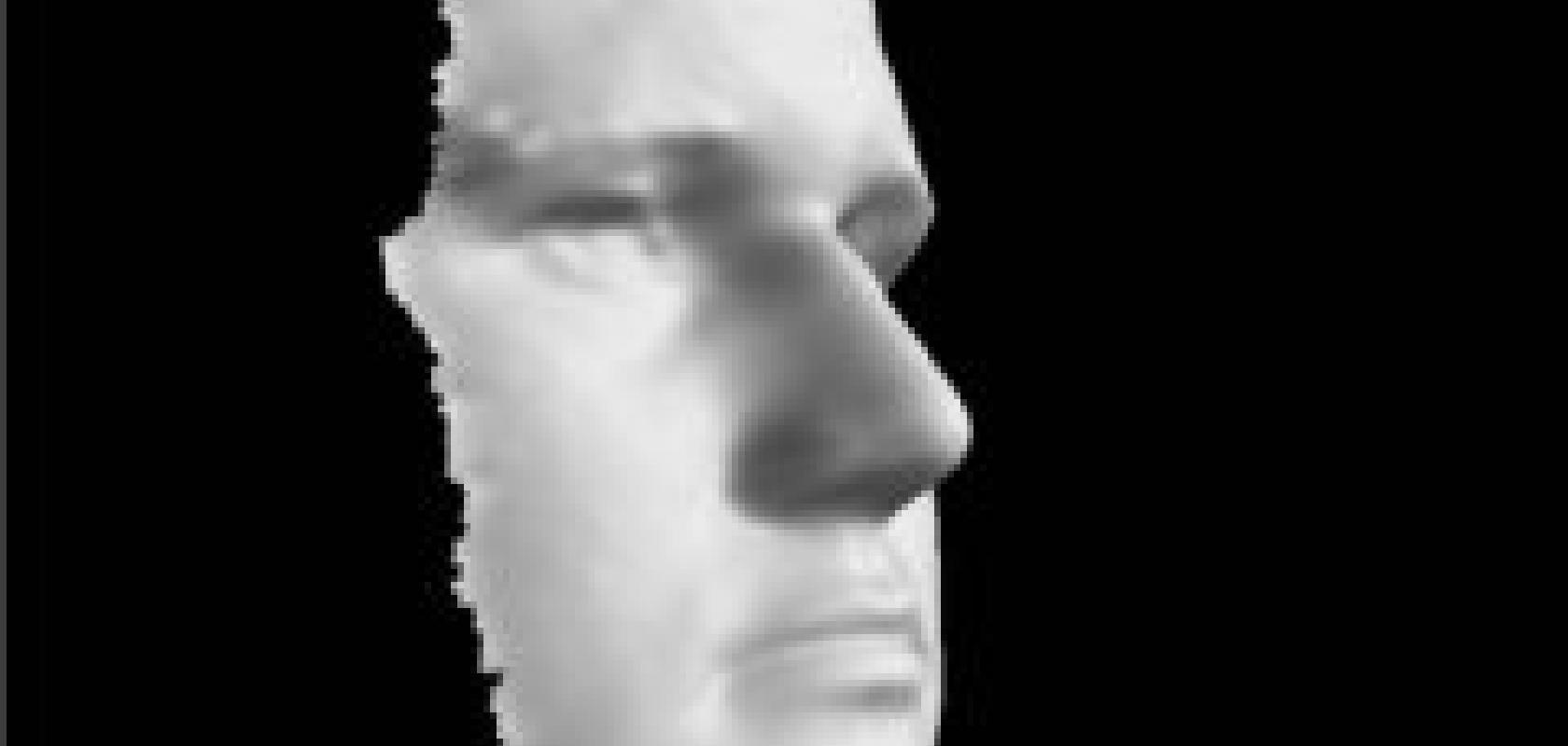
Face-recognition systems work by measuring several unique characteristics of the face. This includes distance between the eyes, length of nose, and the angle of the jaw. The system creates a profile of each individual based on around 30 such characteristics. This is then compared to profiles already held within an image database.
Screen shot produced by A4Vision's 3D Face Reader.
A number of companies, such as A4Vision, Genex and 3DBiometrics have developed 3D face-recognition systems that have been deployed by public authorities. They capture far more data about the face than 2D systems, typically acquiring around 1,000 data points from each face scanned. They are also reliant on high-resolution digital cameras. Using existing analogue monitoring cameras can create problems with jitter and noise. 3D cameras process a number of images and use the composite for greater accuracy.
A4Vision’s systems employ a 3D surface scanner that utilises a near-infrared laser and structured lighting methods. One advantage of using near-infrared is that the system works effectively in poor lighting. Up to 20 frames a second can be captured, building a map of the face of around 20,000 data points. A4Vision’s systems are used by government departments including the US Department of Homeland Security and Singapore’s Immigration Service.
Although 3D measurement and structured lighting are already well established techniques for quality control, improvements in both technology and software are extending its capabilities and opening up the new applications described in the main article.According to Ben Griffiths, from Laser Components, key recent developments include improved line-generation algorithms and shorter wavelength lasers. ‘Current structured-light lines typically display a Gaussian distribution – brighter at the centre, trailing off at the edges,’ he said. ‘This is a source of potential errors. But it also increases cost and slows down image acquisition. Gridlines with Gaussian characteristics require computer pre-processing to correct potential errors. Homogeneous line generation – such as in Laser Components’ HOM series – produces a line that is equally distributed and without Gaussian characteristics. The benefit is faster image acquisition, greater accuracy, and less computer pre-processing.’
Ian Alderton, from Alrad, also emphasises the importance of non-Gaussian line production. But he also points to developments in camera technology. ‘The advent of low cost FPGAs is making a real difference in quality,’ he said. ‘In the past, we were stuck with typically fewer than five frames per second. In practice, this often meant inspection couldn’t be performed as part of the production process, leading to increased cost and reduced quality control. Now, with cheaper FPGAs present in the cameras, we’re seeing all-digital processing taking place right in the camera. That improves quality and increases image acquisition to around 25 to 30 frames per second. The upshot is that automated QC inspection can now take place in situ, online, without stopping the production process. The result is better QC and higher production throughput.’