Ophir Pyro OEM Sensors – What options are available?
1. Advantages of Ophir OEM Pyroelectric Sensors:
Flexible design and faster time-to-market:
These new OEM sensors are based upon a standard design, and their characteristics are controlled digitally. Therefore they give greater flexibility in output options before, while at the same time requiring less engineering effort, so faster time to market is now possible.
More flexible output options:
The Ophir line of OEM sensors includes the following options: raw output from a simple Pyroelectric crystal, smart sensors that can connect to Ophir smart meters, stand-alone sensors with analog output and now for the first time stand-alone sensors with RS232 (or USB) output that can be controlled remotely from the customer’s computer system.
Higher repetition rates, wider energy range:
The new sensors can measure pulses from single-shot up to 25kHz (when connected to one of Ophir’s smart meters), 19kHz with analog output or up to 1.9kHz with RS232 output. Pulse energies can be measured from below 1uJ up to above 40J, depending on the choice of sensor.
Long pulses, wide wavelength spectrum:
Laser pulses of up to 20ms (and in the near future 100ms) with wavelengths from UV to deep IR can be measured by Ophir Pyroelectric sensors.
Adjustable trigger threshold:
The customer can adjust the trigger threshold (via RS232) in case external noise is causing false triggering of the sensor.
Flexible mechanical configuration:
The sensors described below include variations of standard Ophir catalog sensors with electronics built into the sensor, special mechanical designs with electronics inside to fit the customer's requirements or where space is limited, a small custom sensor head with the electronics in a separate module or a sensor head with no electronics.
2. Types of OEM Pyro Sensors:
Today, Ophir offers three broad groups of OEM Pyroelectric sensors


Each of these types is dealt with in more detail below.
3. Analog Output OEM Sensors:
Analog Output sensors provide an analog output voltage proportional to the pulse energy measured by the sensor. The output can be used to drive the customer’s measurement equipment, for example a scope, voltmeter or data acquisition A-to-D board. The output can drive any load greater than 10KΩ with less than 1% loss of accuracy.
3.1 Output Voltage Scales:
The voltage of the pulse is proportional to the pulse energy and can be scaled to whatever full-scale voltage the customer requires. There is the possibility of several energy ranges with the sensitivities of the different ranges arranged in decades or if desired in some other arrangement as in the examples below.
Example 1:
A sensor contains two energy scales, 100mJ, 20mJ. The customer requires the same sensitivity of 100V/J for both energy scales. The full scale volts and sensitivity will be as follows:
Scale Full-scale volts Sensitivity (V/J)
100mJ 10V 100V/J
20mJ 2V 100V/J
Note: To allow a 10V full-scale, the power provided by the customer must be 11v min or 12v typical. The maximum input power is 12v except under special circumstances.
Example 2:
A sensor contains two energy scales, 20J, 2J. The customer requires the same output full-scale (5V) for both scales, so the sensitivity of each scale must be different. The full scale volts and sensitivity will be as follows:
Scale Full-scale volts Sensitivity (V/J)
20J 5V 0.25V/J
2J 5V 2.5V/J
Note: In order to support a given full-scale volts, the power supply provided by the customer must be 1v above the full-scale volts requested. For example,
3.2 Output Hold Timing:
Two output modes are offered to customers with analog output: “fixed hold-time” and “hold until next pulse”.
a) Fixed Hold Time:
In this mode, the output voltage is held active for a fixed time after the pulse is measured, and then drops back to zero.
The fixed hold time can be set to any length as long as it is shorter than the sum of the time between pulses and the pulse integration time.
Note: For sensors supporting a long pulse width, or sensors with a slow response time such as BF or BB coating that require a long measurement time, the analog output might react several milliseconds after the pulse arrives on the sensor.
Note: The Analog Output takes approximately 3us to reach its maximum voltage after being updated. If loaded with extra capacitance by the user’s equipment, this time may be lengthened.
b) Hold Until Next Pulse:
Another mode available is “Hold Until Next Pulse”. In this case the pulse is held at the same level until the next pulse arrives, and then is updated to reflect the new pulse. Using this method, it is not always possible to see when a new pulse arrived, so this mode is probably not as useful as the Fixed Hold Time mode.
c) Digital Output:
In addition to the Analog Output as described above, a digital output (0 to 5v) can also be made available to the customer. The digital output is set LOW when a pulse is triggered inside the sensor, and high when the sensor has finished measuring the pulse. This can be used by the customer as a trigger output or simply to determine when the pulse actually arrived at the sensor, as the Analog Output itself will only react after the sensor has finished measuring the pulse, which in some cases can be up to several milliseconds after the pulse starts.
3.3 Control Options For Analog Output Sensors:
In some cases, where only one energy scale and one wavelength calibration point is provided, no control of the sensor is necessary by the customer. But in other cases, some limited control of the sensor may be necessary by the customer, for example to select between two energy scales, or two wavelength calibration points.
In these cases, a digital control pin is made available to the customer that can be used to control one of a number of binary (on/off) options as described below. The control pin has to be set to TTL logic low or high levels (below 0.4v for “low” or above 2.4v for “high). The logic can be set positive or negative as required (either low or high can set the option on).
The controls available to the customer are listed below. Only ONE of these options can be offered for any given sensor:
- Choose between two energy scales,
OR:
- Choose between two different wavelength calibrations
OR:
- Choose between two pulse width options
OR:
- Choose between diffuser in or out (for a sensor with detachable diffuser)
In addition, an OEM sensor can be designed that in addition to it being used as an analog output sensor, it can be also connected to a smart sensor using a special adapter. This is useful for instance for service staff to hook up to the sensor to make measurements.
3.4 Combining Analog Output and RS232 Control:
In some cases using a single control pin to choose between two options will not be sufficient. Examples of this might be one of the following:
- If the sensor has more than two energy scales
- If the sensor has more than two laser wavelengths
- If the sensor requires control of two different parameters, for example energy scales and wavelengths, or energy scales and pulse width
In any of these cases a “combined” sensor with both Analog Output and an RS232 connection can be supplied to the customer. The measurement will be provided via the Analog Output for the customer’s convenience, but the control will be via RS232 to allow selection of multiple options.
4. RS232 OEM Sensors:
Another option available for customers is RS232 output. In the simplest case, a male D9 connector is provided which connects directly to a PC female COM port connector. Provision is made with separate wires or a separate connector to provide power and ground.
Alternatively, a D9, D15 or other custom connector type is provided with custom pin-out, and the customer can deliver power (typically 5v, up to 12v max) and also connect RS232 Tx and Rx lines to their PC according to their requirements.
In the case of RS232 sensors, the output and control is provided via RS232 commands. A complete set of commands is listed in the sensor spec sheet.
As mentioned above, if necessary an Analog Output can be added to an RS232 sensor to provide an addition output option for the customer.
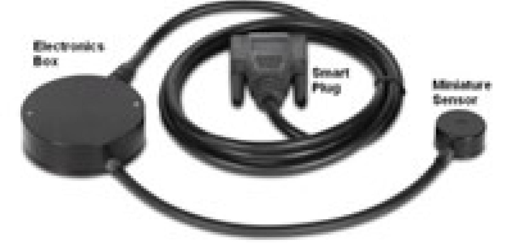
5. Other Types of OEM Sensors:
As mentioned above, another option is to provide “smart-plug” OEM sensors which connect to a smart meter such as the Nova-II via a D15 smart-plug. These are variations on our line of standard PE-C catalog sensors, but with some modification specific to the customer. Modifications to the standard sensors might include one or more of the following:
- Calibrated only at one or more specific wavelengths
- A specific set of energy ranges
- Changes in mechanical design
In addition, simple pyroelectric sensors with no electronics can be provided, with flexible mechanical design. This option is the lowest cost, but has the lowest available performance.
6. Summary:
We have seen that today many types of OEM sensor can be provided by Ophir with a lot of flexibility in the output format. We can offer Analog Output with various full-scale volts or hold timing; RS232 allowing remote control; or smart-plug sensors with variations from the standard line of Pyro-C sensors as necessary. We can offer various standard and custom mechanical designs including with the electronics built in or separate.
In addition to all of these options, the OEM Pyro-C family have all the other outstanding standard features of the Pyro-C family of sensors: Multiple pulse width options including very long pulse widths in excess of 10ms, user threshold adjustment, the ability to measure pulses with a very high duty cycle (approaching 50% in some cases). These unique features, along with some of the highest damage threshold and average power specs available in the industry, make Ophir sensors the first choice for standard and OEM Pyroeletric sensors.
