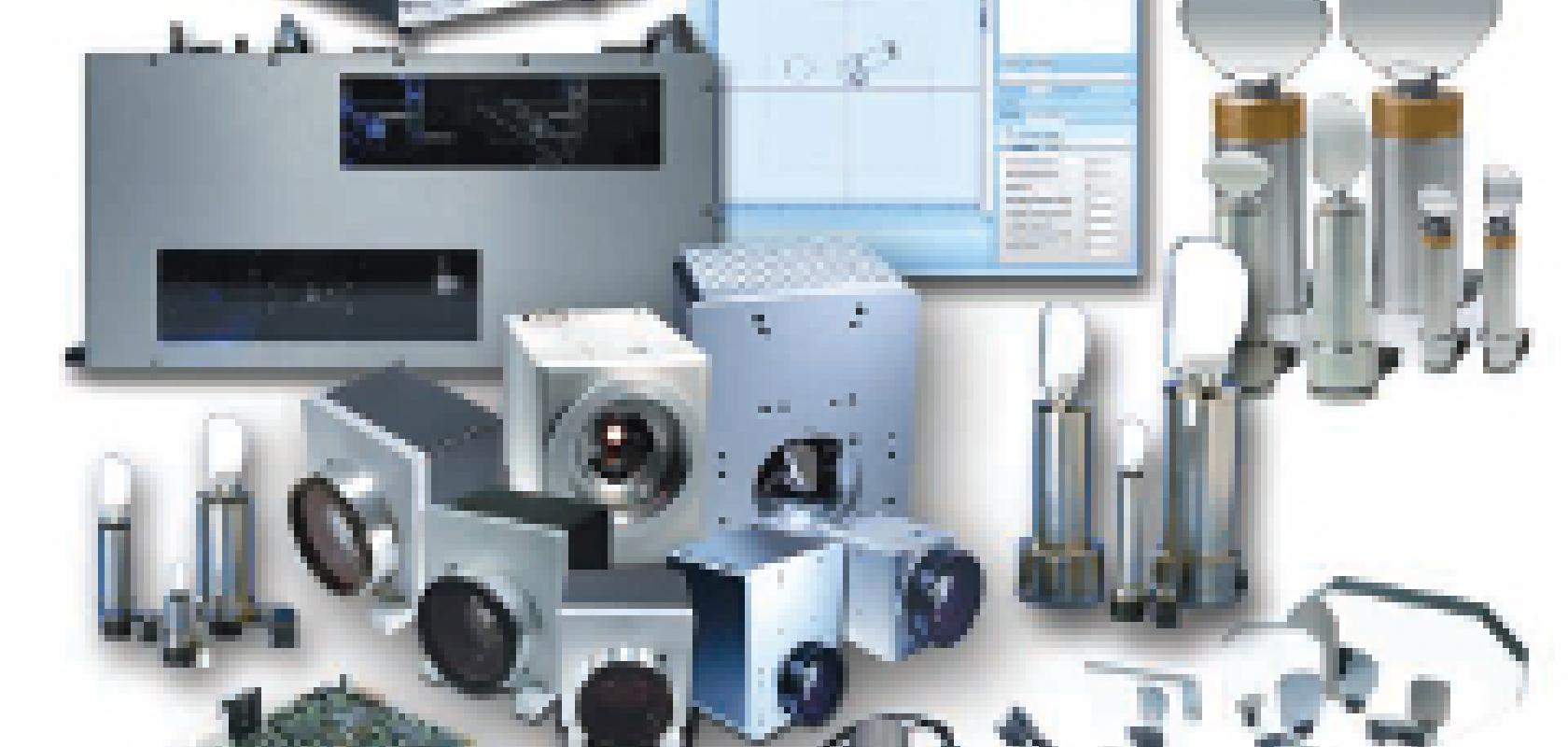
‘Most laser applications began with a fixed laser beam and a positioning stage that moved the part underneath the beam. This is way too slow to be economically viable for most applications,’ says Georg Hofner, chief executive officer at Scanlab, which manufactures laser scanning devices. Those applications where fast means economically viable range from marking to solar power, and scanning can make the difference,.
The widespread adoption of solar power is going to rely on engineers increasing the sunlight conversion efficiency and making the photovoltaic cell manufacturing process much cheaper. Hofner explains how a scanning system manages to be fast enough to deliver economic improvements to the likes of photovoltaics. ‘The scanning system is only moving small mirrors, which positions the beam large distances relative to the movement of the mirror. Scanning heads are therefore dynamically much more advanced than what you can do with a linear stage.’
One example of this speed is the recently completed Solasys project. Coordinated by the Fraunhofer Institute for Laser Technology in Aachen, Germany, Solasys demonstrated 10,000 holes per second laser drilling in metal wrap-through (MWT) and emitter wrap-through (EWT) techniques. This technology is designed to lower the proportion of a crystalline silicon solar cell covered by conducting wires and thereby improve efficiency.
Other scanning laser applications are eye surgery and diagnostic retinal scanning. These have to be very precise with excellent reliability and accuracy. Industrial laser processing is another sector. The scanners themselves can range in price and complexity, from simple scan heads for marking costing $500, to three-axis, high-end systems that might reach $50,000.
Two-axis systems have an x and y axis perpendicular to one another. As the x and y axes are typically closed-loop and servoed, they can be programmed to cover any spot in a scanning area. ‘The type of laser processing will depend on the size of the aperture,’ explains Red Aylward, president of Cambridge Technology. Larger apertures with a large mirror will give a small, focused spot, but the beam will be manipulated at a slower speed. It depends on the application as to the size of the aperture used.
‘These mirrors move extraordinarily fast,’ Aylward states. ‘Scanning systems can drill 3,000 holes in a circuit board in one second with a small spot size and very fine positioning. The beam has to accelerate to a position, stop, drill the hole, accelerate to the next spot and drill the hole, 3,000 times a second.’
Cambridge Technology provides 28 models of galvanometers, including open-loop, closed-loop and resonant varieties, plus scan heads, controllers, and scanning subsystems. They cover clear apertures from 1 to 100mm, laser powers from milliwatts to several kilowatts, and wavelengths from deep UV to the far infrared.
Most galvanometers are closed-looped systems, which have a positioning feedback device built into them. ‘A lot of the performance of the galvo is dependent upon the precision of the feedback device, in terms of its accuracy, its thermal stability, its noise floor, and repeatability,’ says Aylward.
Adding a z-axis
Adding a third axis makes the system more complex, but allows 3D geometries to be processed. In two axis systems, an f-theta lens is used to alter the focal point dynamically as the beam sweeps over the workpiece. David Freihofer, director, optical scanning components at Cambridge Technology, explains: ‘As the galvo is scanning back and forth, the focal point of the beam is making an arc across the scan field. Therefore, with a flat workpiece, you need to be able to flatten that focal field; the beam has to remain focused as it scans across the workpiece.’
In a three-axis system, the f-theta lens is replaced with a pre-scanning objective system that dynamically focuses the beam along the z-axis. Erwin Wagner, chief technical officer at Raylase, notes that one advantage with incorporating a dynamic lens for the z-axis is that a range of field sizes can be covered. An f-theta objective, on the other hand, provides a fixed focal length, which in turn defines the size of the scanning field. Fabricating f-theta lenses covering larger working areas becomes very expensive, and a dynamic lens for the z-axis increases the field of view. Raylase manufactures scanning systems and components. It has supplied three-axis systems for scanning fields of up to 2 x 2m.
Micromachining
In most laser systems the scan head will be synchronised with a linear positioning stage. ‘To position the beam correctly, the galvo axis and linear axis have to be synchronised,’ explains Daniel Schwab, responsible for project engineering and hardware development at Arges, a laser scan head provider. ‘The encoder signal of the linear stage is transmitted to the scan head controller in order for it to calculate the mirror position and position the beam accurately during the movement of the stage.’ Arges also builds controllers for laser systems to synchronise linear stages and scan heads.
The company has recently introduced its Anteater three-axis scanning system, suited to applications like micromachining requiring high-speed scanning. The Anteater scanning system incorporates small mirrors for high-speed processing and can be used with picosecond lasers for cold ablation. How well the scan head is synchronised with linear or rotary stages can impact upon the precision of the laser system, which is crucial for micromachining tasks and creating very small features on the part. US company, Aerotech, has released the Nmark CLS scan head controller, aimed at high-end laser micromachining applications.
‘The previous generation of the product, the Nmark SSaM, supports a mature serial communication interface called the XY2100, which is available with almost all commercial scan heads,’ explains Ron Rekowski, advanced automation division manager at Aerotech. ‘The limitation with this serial control protocol is that the exact location of the galvo is unknown. From a programmer’s perspective, the protocol is open loop – the command is sent and you have no idea how long it takes to arrive or what the profile looks like. That’s been a historic problem with galvos.’
To get around this, Rekowski says, galvo suppliers implemented various overheads in their programming such as jump delays, mark delays, and polygon delays. These delays are implemented to ensure the galvo reaches a certain position before switching the laser on or off.
There are some inherent shortcomings in this, according to Rekowski. ‘We come from the high-precision laser processing area, but working with linear positioning stages,’ he says. ‘We always know where the stages are positioned; we have direct access to the feedback of the stages. What we tried to do was develop a product that treated the scanner just like a servo axis. What that required was to ditch the XY2100 serial communication protocol, instead accessing the feedback of the galvo directly. By doing this we know exactly where the galvo is positioned at any given point in time. This means a lot of these programming concepts are redundant. Now, because we know the position of the galvo, we can automatically turn the laser on and off at the right position.’
In addition, Rekowski says, because the controller has access to the feedback, the laser can be triggered as a function of position. ‘Historically that’s never been done. Typically, the laser was fired at a constant repetition rate and, as the mirrors accelerated and decelerated, there was a change in overlap of the laser pulses – the pulse rate was fixed, but the material was moving at a variable rate so the spacing of the laser pulses changed.’ The Nmark CLS triggers the laser as a function of position, so when the mirrors accelerate or decelerate the controller will speed up or slow down the trigger rate of the laser to ensure the pulses are positioned precisely.
Ultrafast pulses
The emergence of ultrafast laser technology, pulsing on the order of picosecond or femtosecond timescales, is driving the development of scanning systems. Hofner at Scanlab comments that the company is working on scanners for ultra-short pulsed lasers.
Ultrafast lasers can be used for cold ablation, which doesn’t produce any noticeable heat affected zone on the material. But in order for them to operate in this way, each pulse has to be separated to avoid putting excess energy into the part. To ablate the material, the laser has to pass over the surface several times, but the pulses always have to be separated.
‘These ultra-short pulsed lasers reach very high frequencies of several megahertz to get reasonably high power,’ Hofner says. ‘At these frequencies, the scanning optics have to move extremely fast. This is a real challenge for scanner technology to reach these high speeds and maintain the accuracy of the system.’ He adds that ultra-short pulses put high power densities into the optics and specialised fabrication and coating methods are employed for them.
The PSO (position synchronised output) programming environment developed by Aerotech for the Nmark CLS allows a better registration between successive pulses on each pass, because the laser is pulsing based on the position of the stage. In addition, Rekowski says the scanner using the Nmark CLS controller provides high accuracy and repeatability. ‘Traditional scanners aren’t necessarily that accurate,’ he states. ‘They have thermal drift issues and long term repeatability problems.
‘If you’re working with an ultra-high speed laser and you’re trying to make features on the scale of tens of microns wide then accuracy and repeatability becomes critical,’ he says. ‘We deal with these types of accuracies all the time with our precision linear stages. We’re trying to apply that same positioning capability to a scanner.’
According to Rekowski, historically, customers have struggled to get on the order of 10µm accuracy over a field size of 150 x 150mm. With a high-quality set of x-y stages though, that’s not difficult to achieve.
The tradeoff with using x-y stages is that they don’t have the throughput that a scanner would. ‘We want to improve the accuracy of the scanner such that we can get better than 10µm over a 150 x 150mm field of view,’ Rekowski comments.
The other advantage of tying the scanner and servo axes together with a common programming language is the elimination of stitching errors in larger parts. Traditionally, high-precision scanners would use a small field size – of 100 x 100mm, for example – to keep the accuracy high. A part 300 x 300mm would therefore have to be processed in nine 100mm sections. In this instance, stitching errors, when moving from one section to another, can occur due to the angular motion that occurs during the x-y stage motion.
Since the scanner and servo are both controlled directly with the Nmark CLS in the same programming environment, the customer can program in one continuous 300mm x 300mm programming space. ‘The field of view is not fixed to the operational area of the scanner,’ says Rekowski. ‘You don’t need to break a continuous scan into smaller segments according to the field of view of the scanner.’
Speed and accuracy remain important factors in laser scanning devices for high-precision micromachining tasks. And with the emergence of ultrafast lasers further increases in speed will be required to keep up with the pulse rate.


