Microsoft’s Bernard Kress, who chaired the AR/VR/MR industry days at SPIE Photonics West, considers the optimal way of designing optics for augmented and mixed reality headsets
Augmented reality, and especially mixed reality systems – MR is a form of AR that augments the real world with virtual objects – are poised to become the next computing and communication platforms, replacing the ailing desktops and laptop devices, and even the now aging tablets and smartphones. Such systems need to be untethered, and require high-end optics for the display engine and the combiner, as well as for the sensors – depth scanners, head tracking cameras to provide six degrees of freedom, universal and accurate eye trackers, and gesture sensors. These are, today, the most demanding headsets in terms of optical hardware[1] [2].
Three categories of head mounted displays have emerged: smart glasses, or digital eyewear, as an extension of eyewear; virtual reality headsets as an extension of gaming consoles; and augmented and mixed reality systems as an extension of computing hardware.
Eventually, if technology permits, these three categories will merge into a single hardware concept. This will, however, require major improvements in connectivity (5G, WiGig), visual comfort (new display technologies), and wearable comfort (battery technology, thermal management, weight and size).
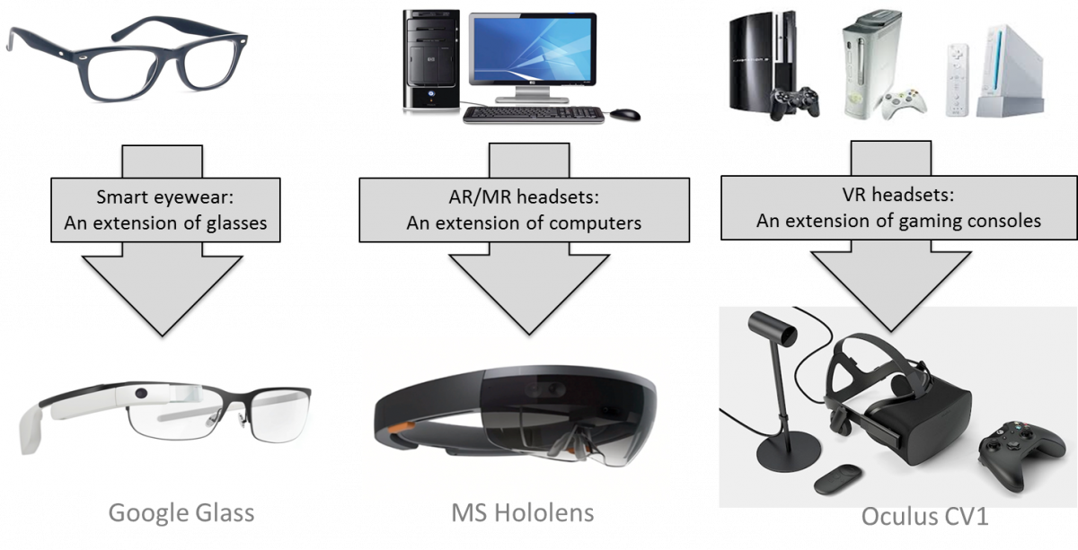
Figure 1: The three types of head-mounted displays
The worldwide sales decline for smartphones and tablets, as of Q3 2018, is an acute signal for venture capital firms and major consumer electronics corporations to fund and develop the ‘next big thing’, whatever it may be. Mixed reality systems stand out as a good candidate.
Apple, Microsoft, Google, Facebook, Intel, Amazon and Huawei all have active internal AR/MR development programmes, some in more stealth mode than others. Furthermore, all agree that the optical hardware has yet to evolve to a point at which it would make it possible to offer the ultimate MR experience to the consumer, both in performance and cost[3].
The ultimate MR experience calls for various improvements in comfort (wearable and visual) and display immersion. Such optical challenges can only be met through an optical design procedure that puts the human visual system at its core[4], a process AR designers call human-centric optical design. The performance and limitations of the human visual system are very different from that of computer vision systems.
Knowledge of human binocular vision can be used to reduce the complexity of the optical hardware, as well as the software and content structure, without degrading the user’s display immersion and comfort experience.
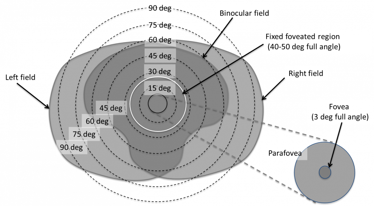
Figure 2: Human binocular field of view showing the different visual regions
The human fovea – responsible for sharp central vision, where resolution perception is at a maximum thanks to its high cone density – covers only 2° to 3°, and is set off-axis from the line of sight by about 5°.
The fovea is a result of early life visual experience, and grows from a young age to form a unique area set apart from the line of sight.
The human vision system operates based on the cone and rod density over the retina. The optical axis or pupillary axis, normal to the vertex of the cornea, is slightly offset from the line of sight by about 5°, and coincides with the location of the fovea on the retina. The blind spot, where the optic nerve is located, is offset by about 18° from the centre of the fovea.
Figure three shows the horizontal extend of the different angular regions of the human binocular vision system. Although the entire field of view (FOV) spans more than 220° horizontally, the binocular range spans only 120° in most cases, depending on the nose geometry[5] [6]. Stereopsis, or depth perception from fusing the left and right monocular vision is, however, more limited to +/-40°.
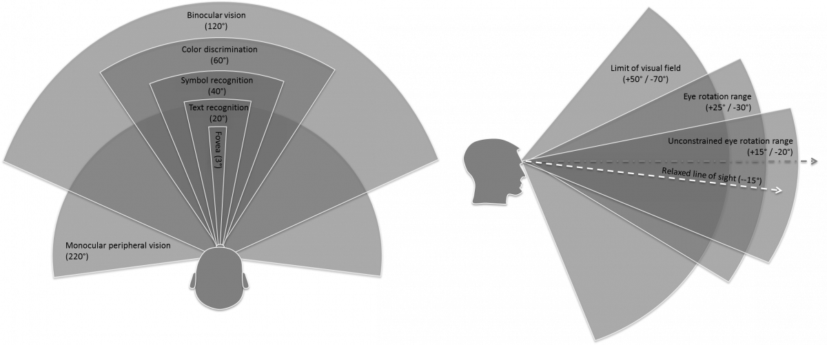
Figure 3: Extends and specifics of the human visual field
The binocular field of view is a reasonably large region, horizontally symmetric and vertically asymmetric, spanning +/-60° over +55° upper and -30° lower, with a central lower region reaching also -60°, but over a smaller horizontal span of 35° full angle.
The fixed foveated region over which sustained eye gaze is possible, defines the state-of-the-art diagonal field of view for most high-end AR/MR devices today, which also provide a 100 per cent stereo overlap. Furthermore, for a given gaze angle, colour recognition spans a +/-60° FOV, shape recognition over a +/-30° FOV, and text recognition over a much smaller field of view of +/-10°.
The vertical FOV is similar in size to the horizontal FOV, and is set off-axis from the standard line of sight, by about 15° downwards (relaxed line of sight).
The human field of view is a dynamic concept, best described when considering the constrained and unconstrained eye motion ranges – the unconstrained eye motion does not produce eye strain and allows for steady gaze and subsequent accommodation reflex. This can vary depending on age[7].
While the mechanical eye motion range can be quite large (+/-40° horizontal), the unconstrained eye motion over which gaze is possible, without inducing the head turning reflex, is much smaller, roughly +/-20° FOV horizontal. This defines the static foveated region, ranging between 40° and 45° FOV horizontal.
The field of view in an immersive display system is the angular range over which an image can be projected in the near or the far field. It is measured in degrees and the resolution over the field of view is measured in pixels per degree[8].
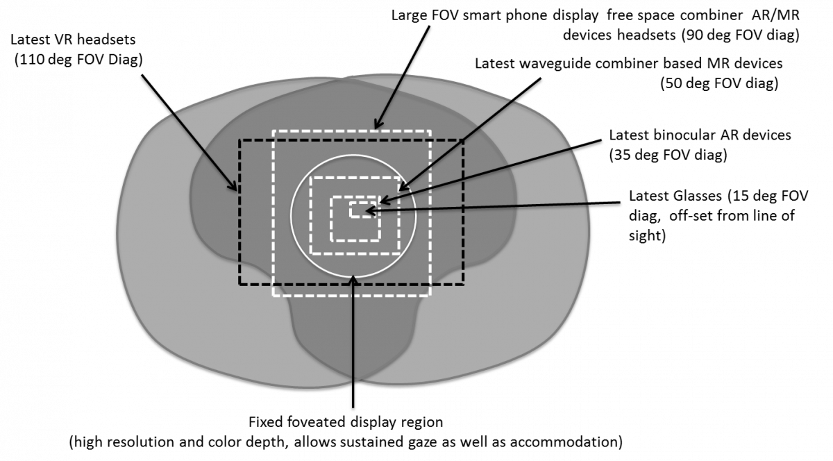
Figure 4: Field of view of various head-mounted displays superimposed on the human binocular field of view
Standard VR headsets (Oculus CV1, HTC Vive, Sony Playstation, Microsoft Windows MR) all have fields of view of around 110° diagonal, stretching towards 200° for some others (PiMax and StarVR).
Large AR field of view of up to 90° can be produced by a large cell phone panel display, combined with a large single curved free space combiner (Meta2, DreamGlass, Mira, NorthStar Leap Motion), while smaller field of view high-end AR/MR systems use microdisplay panels, such as Microsoft HoloLens V1 and Magic Leap One.
Smaller smart glasses typically have fields of view ranging from 10° to 15° (Zeiss Smart Glasses, Google Glass) to 30° to 40° (Optinvent ORA, Lumus DK50, ODG R8).
In order to optimise an HMD for a large field of view, the various regions of the human FOV described in figure three have to be considered in order not to overdesign the system. By employing a human-centric optimisation and cost function, an optical system can be designed that closely matches the human vision system in terms of resolution, modulation transfer function (MTF), pixel density, colour depth and contrast.
Optical building blocks
Now that we have analysed the specifics of the human visual system, we are ready to start designing the display system and optical architecture. A typical functional optical building block suite of an MR system is shown in figure five.
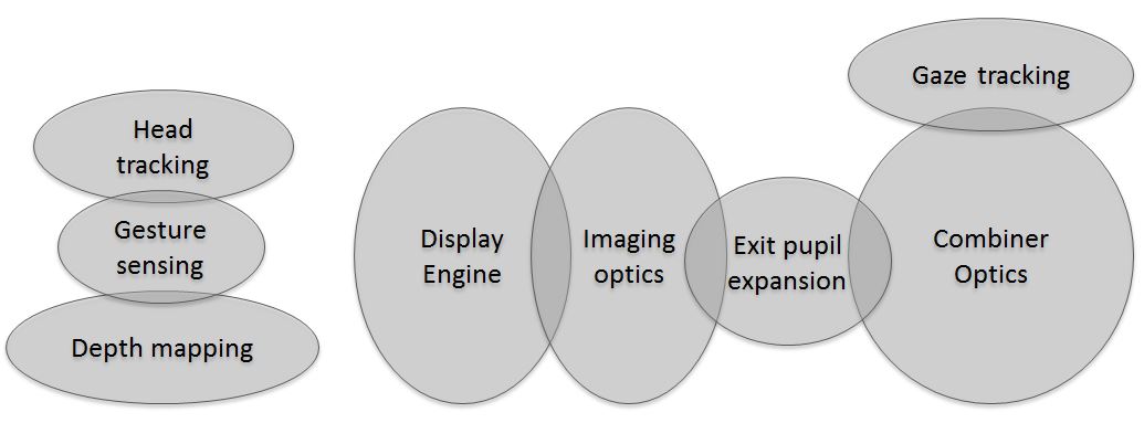
Figure 5: Optical building blocks of a mixed reality headset system
The display engine is where the image is formed, and then imaged onwards, forming a pupil (or none), through an optical combiner, which can include a pupil replication scheme, to the eye pupil. Gaze tracking might or might not share optics with the display architecture – the display system is usually an infinite conjugate system, the eye tracking system is usually a finite conjugate system. Head tracking, gesture sensing and depth mapping rely on external sensors (such as time of flight and cameras).
Display engine
Early 1990s VR and smart glass display engines were based on 1D LED scanners, such as in the 1989 Private Eye smart glass by Reflection Technologies and VR Boy by Nintendo (1995). Cathode ray tube display units were used early on in VR, as well as AR systems (Sword of Damocles, 1968), and are still in use in some of the high-end defence AR headsets today, as in the current Apache Helicopter AR monocular headset.
Later, microdisplays[9] using free space illumination systems – and later backlights or frontlights – have been used in both smart glasses and AR headsets, such as high temperature poly-silicon LCD (Google Glass), liquid crystal on silicon (Lumus, HoloLens, Magic Leap) or digital light processing (Digilens, Avegant). Emissive 2D microdisplay panels have also been used extensively, such as OLED displays (ODG R9, Zeiss Smart Glasses). Higher brightness iLED microdisplays[10] are poised to revolutionise AR optical engines by providing the brightness (tens of thousands of Nits) and contrast required to compete with outdoor sunlight, without the use of a bulky illumination system.
More recently, 2D MEMS laser or vertical-cavity surface-emitting laser (VCSEL) scanners, (Intel Vaunt, Thalmic Labs, QD laser) have proven to reduce dramatically the size of the optical engine. Redesigning the older 1D scanners with today’s iLED and MEMS technology could prove to be an interesting solution to reduce the size of the optical engines and increase brightness or contrast. Other scanning technologies, such as fibre scanners[11], integrated electro-optic scanners, and surface acoustic wave (SAW) scanners have also been investigated.
It is noteworthy that laser-based phase panel display engines, i.e. dynamic holographic projectors, which have entered the market through automotive head-up displays (HUDs) thanks to their high brightness, have recently been applied to the design of interesting display architectures that can provide a per pixel depth display[12].
This also effectively solves the vergence accommodation conflict (VAC) present in most immersive 3D stereo vision systems[13]. Phase panels can come in many forms, from liquid crystal on silicon (LCOS)-type platforms to MEMS pillar platforms.
Most of the scanner and phase panel-based optical engines lack in eyebox, the region over which the entire field of view is visible to the user.
They therefore need complex optical architectures to extend, replicate or steer the exit pupil to the user’s eye.
Imaging optics
Once the image is formed over a plane, a surface or a volume, or through a scanner, an exit pupil has to be formed, over which the image is either totally or partially collimated, and presented directly to the eye or to an optical combiner. In some cases, an intermediate aerial image over a diffuser can also be formed to increase the etendue of the system.
Forming spatially demultiplexed exit pupils – either colour or field separated – can be an interesting option, depending on the combiner technology used. Imaging optics in the display engine are usually based on traditional free space optics but in compact form, including typically polarisation beam cubes (PBS) combined with catadioptric birdbath optical architectures[14] to fold the optical path in various directions.
Combiner optics and exit pupil expansion
The optical combiner is very often the most complex and most costly optical element in the entire MR display architecture; it is the one seen directly by the user and the one seen directly by the world. It often defines the size and aspect ratio of the entire headset. It is the critical optical element that reduces the quality of the see-through, and the one that defines the eyebox size, and in many cases also the field of view.
There are three types of optical combiners used in most MR/AR/smart glasses today: free space optical combiners; total internal reflection (TIR) prism optical combiners with compensators; and waveguide-based optical combiners.
One important point to remember when designing an HMD display system is that the optical engine has to be optimised in concert with the combiner engine. Having a team designing an optical engine without fully understanding the limitations and specifics of the combiner optics designed by another team, or vice versa, can result in a sub-optimal system or even a failed optical architecture, no matter how well the individual optical building blocks might be designed individually.
Circumventing etendue
There are various challenges to overcome in order to provide: a large field of view and wide stereo overlap; a large eyebox; a large eye relief allowing prescription lens wear; a high angular resolution close to the 20/20 vision; and a small form factor, low weight, and a centre of gravity close to that of the head.
According to the law of etendue (Lagrange invariant), when one attempts to expand the field of view by increasing the numerical aperture of the collimation lens, the eyebox gets reduced (as well as the resolution), and the size of
the optics increases dramatically.
In an optimal system, it is interesting to have all four parameters maximised at the same time, calling for compromises as well as alternative optical architectures, carefully tuned to the specifics and limitations of the human visual system.
When tasked with designing an optical combiner, the optical designer has to check out various requirements, first with the user experience team, which will indicate the interpupillary distance (IPD) to cover – i.e. the target population for a single SKU – as well as with the industrial design team, which will indicate the minimum and maximum size of the display and combiner optics.
Figure six depicts how a design space can be defined over a graph showing the combiner thickness as a function of target eyebox size (IPD coverage).
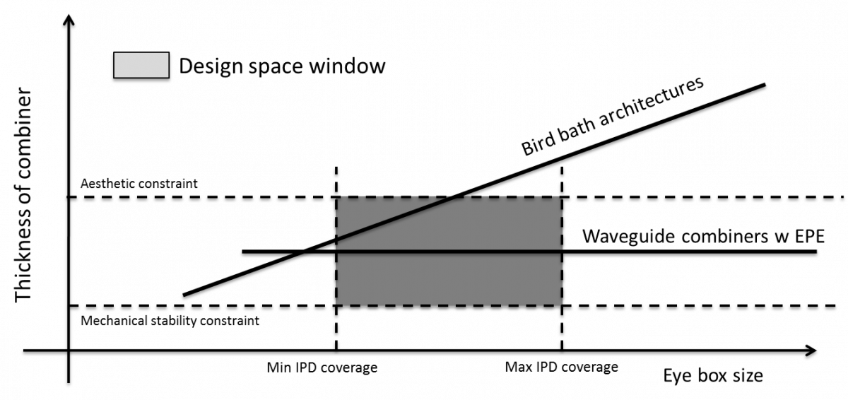
Figure 6: Typical design space for specific interpupillary distance coverage and ID requirements
The minimum and maximum IPD values, as well as the minimum (for mechanical rigidity) and maximum (for aesthetics and wearable comfort) thickness of the combiner define a window space (grey window in figure six) over which the optical designer needs to design the optical combiner.
When contemplating using a birdbath optical architecture (Google Glass, ODG R9, Lenovo AR), simple in nature and relatively cheap to produce in volume, the size of the optics becomes proportional to the eyebox (and also the field of view), and thus cannot usually satisfy the design window constrains anymore. Mechanical IPD adjust might help to cover the design window, but this produces other constraints, which can be even more critical. When contemplating the use of a waveguide combiner, one can notice that the waveguide thickness does not change when the eyebox increases (figure six).
The lateral size of the waveguide combiner, however, increases with both field of view and eyebox. This is one reason why many AR/MR designers choose to use waveguide combiner architectures for AR/MR HMDs that need to accommodate a large population and at the same time produce a relatively large field of view. This is a difficult choice to make, since often it is also the most complex and costly element on the optical stack.
As if this was not limiting enough, the law of etendue stipulates that the product of the microdisplay size multiplied by the numerical aperture of the display engine, equals the product of the field of view multiplied by the perceived eyebox (exit pupil). (Microdisplay size) x (Display engine NA) = (Eyebox) x (FOV in air).
As size matters, designing the smallest optical engine (small display aperture size and low NA lenses), while achieving a large field of view over a large eyebox, would rather call for the following equation: (Microdisplay size) x (Display engine NA) < (Eyebox) x (FOV in air).
According to the law of etendue, this is not possible. However, as the final sensor is not a camera but rather the human visual system, various tricks can be played to circumvent this principle, in various dimensions (space, time, spectrum, polarisation, etc). This is in line with the principle of human-centric optical design.
There are various ways to circumvent the law of etendue. A few different architectural implementations, allowing a larger perceived eyebox by the user than what would be predicted by the strict law of etendue are: mechanical IPD adjust; pupil expansion; pupil replication; pupil steering; pupil tiling; pupil movement and pupil switching.
Mixed reality systems of tomorrow
Matching closely the performances of MR optical system and display/sensor architecture to the specifics of the human visual and sensory system are key to building the ultimate MR headset.
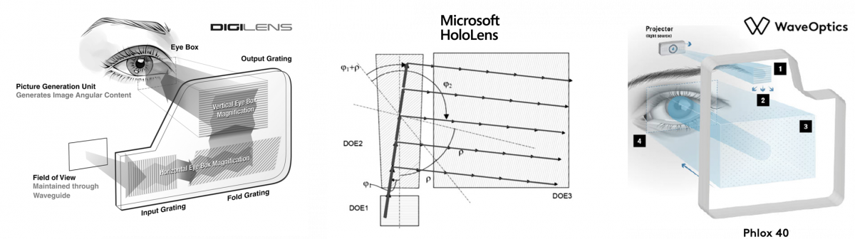
Waveguide combiner architectures implementing two-dimensional exit pupil replication tend to be the de facto building block for tomorrow’s lightweight AR/MR systems, addressing at the same time immersion and wearable comfort, such as in Microsoft HoloLens[14], Magic Leap One, Vuzix Blade, Nokia, Digilens, BAE, WaveOptics. Additional efforts are needed to get costs of such complex waveguide combiners down to consumer levels. Figure seven shows a few of such waveguide combiner elements.
Optical foveation, pixel occlusion, peripheral displays and vergence accommodation conflict are other key issues to solve for visual comfort[15] [16]. They provide the immersive display and sensory experience that would allow not only enterprise and defence AR/MR markets to flourish, but also allow the burgeoning consumer market to reach the expectations of the markets’ analysts. EO
Bernard Kress is partner optical architect for Microsoft HoloLens and a SPIE board member. This article is a section from a white paper Kress wrote that will be the basis for an upcoming SPIE field guide on ‘optical architectures for VR, AR and MR’. The AR/VR/MR industry days at Photonics West will be the largest event in the year for optical hardware in augmented, virtual, and mixed reality; SPIE will host a similar meeting as part of its Digital Optical Technologies conference at the World of Photonics Congress in Munich in June.
References
[1] R. T. Azuma, “A survey of augmented reality :Presence, Teleoperators and Virtual Environments” 6, 355- 385 (1997).
[2] Woodrow Barfield, “Fundamentals of wearable computers and augmented reality”, second edition, ISBN 978-1-
482243595 (2015).
[3] O. Cakmakci, and J. Rolland, “Head-worn displays: a review,” J. of Disp. Tech. 2, 199-216 (2006).
[4] Jason Jerald, “The VR book: human centered design for virtual reality”. ISBN 978-1-97000-112-9 (2016).
[5] Michael F. Deering, “The Limits of Human Vision”, Sun Microsystems, 2nd International Immersive Projection Technology Workshop, 1998.
[6] Antonio Guirao Conception Gonzalez, Manuel Redondo, Edward Geraghty Sverker Norrby and Pablo Artal: “Average Optical Performance of the Human Eye as a Function of Age in a Normal Population” Investigative Ophthalmology; Visual Science:. January 2014. Vol. 40, No. I.
[7] Philip R. K. Turnbull, John R. Phillips , “Ocular effects of virtual reality headset wear in young adults” , Nature, Scientific Reports 7: 16172 (2017)
[8] Brian Wheelwright, Yusufu Sulai, Ying Geng, Selso Luanava, Stephen Choi, Weichuan Gao, Jacques Gollier, “Field of view: not just a number”, Proc. SPIE 10676, Digital Optics for Immersive Displays, 1067604 (21 May 2018)
[9] “Understanding Trade-offs in Microdisplay and Direct- view VR headsets designs”, Insight Media Display Intelligence report, 2017
[10] Zhaojun Liu, Wing Cheung Chong, Ka Ming Wong ands Kei May Lau, “GaN-based LED micro-displays for wearable applications”, Microelectronic Engineering 148 (2015) 98–103
[11] Brian T. Schowengerdt, Mrinal Murari and Eric J. Seibel, “Volumetric Display using Scanned Fiber Array”, SID 10 DIGEST 653 , 2010.
[12] Joel Kollin, Andreas Georgiu, Andrew Maimone, “Holographic near-eye displays for virtual and augmented reality”, in ACM Transactions on Graphic 36(4):1-16 · July 2017.
[13] Martin S. Banks, David M. Hoffman, Joohwan Kim, and Gordon Wetzstein , “3D Displays”, Annu. Rev. Vis. Sci. 2016. 2:19.1–19.39
[14] Bernard Kress and William Cummins “Towards the Ultimate Mixed Reality Experience: HoloLens Display Architecture Choices”, SID 2017 Book 1: Session 11: AR/VR Invited Session II.
[15] Hong Hua and Sheng Liu , “Dual-sensor foveated imaging system”, Applied Optics, Vol. 47, No. 3, 20 January 2008
[16] Anjul Patney, Marco Salvi, Joohwan, Kim Anton Kaplanyan, Chris Wyman, Nir Benty, David Luebke and Aaron Lefohn ,
“Towards Foveated Rendering for Gaze-Tracked Virtual Reality” , ACM Trans. Graph., Vol. 35, No. 6, Article 179, 2016
Related stories
Enlightening reality: With the launch of the Oculus Rift and Microsoft's HoloLens, user adoption of virtual and augmented reality devices is set to increase. Jessica Rowbury looks at how optical modelling is aiding the development of VR and AR systems
Heightened reality: VR experts give optics wish list at Photonics West Greg Blackman reports from a Photonics West panel discussion on virtual reality, where headset optical design will be instrumental for giving a better user experience
