Mobile phone cameras used to be a bit of a gimmick when mobile phones were still used primarily for making phone calls. They’re now rather impressive and also ubiquitous, to the point where some of the most arresting images of world events – the tsunami in Japan and the ‘Arab Spring’ uprising, to name a couple – were taken by mobile phones.
A lot of optical design work has gone into shrinking the optics to fit a mobile phone while optimising the camera sensor, much of which is simulated by optical design software. ‘Cell phone cameras now have excellent zoom ranges and megapixel resolution, all in a tiny package, and millions of these are fabricated per batch. Therefore, you need to control cost and performance and you’ve got to get a lot of capability in a small package, both of which optical design software helps with,’ explains David Hasenauer, Code V product manager at Synopsys.
In October 2010, Synopsys acquired Optical Research Associates and its Code V and LightTools optical software packages, (Code V is for designing imaging systems, such as camera lenses, mobile phone cameras, and satellite reconnaissance systems, while LightTools is for the design of non-imaging and illumination systems, like backlight displays, LED applications and automotive lighting).
Much of the space-savings in mobile phone optics derive from integrating non-spherical optics, which can reduce the number of lenses, complexity and weight of a system. In terms of modelling aspheres, Hasenauer believes one of the most significant advances in optical design software for imaging systems that has occurred in the last couple of years is the development of tools for defining and optimising non-spherical surfaces. The standard mathematical formulation for defining a non-spherical surface, known as a ‘power-series asphere’, is inherently unstable for optimising the performance of a lens system, he feels. He also adds that it requires many digits of precision in the coefficient values, and there’s no feedback to the optical designer about whether or not the asphere would be easy to build and test.
Greg Forbes at QED Technologies in Rochester, which makes optical metrology and fabrication equipment, developed a different formulation called ‘Q-type asphere’. Hasenauer says that this formulation is inherently more stable and has many advantages over power-series asphere tools. Code V 10.3, released in 2011, has features making use of this mathematical form of the asphere.
‘The two main challenges in optical system design are achieving higher performance and making the systems more compact,’ Hasenauer states. Aspheres are a good way to do this and, he says, the Q-type asphere formulation ‘provides new capabilities for optical software engineers’. For example, Code V 10.3 has a feature that determines quickly where one or more aspheres would be most applicable in an optical system, no matter whether it has 10 surfaces or 100 surfaces. There are existing methods to do this but, Hasenauer says, they are much slower.
Optimising an optical system
There are four main functions of optical design software: firstly, being able to model all the various optical components, including lenses, mirrors and gratings. Then there’s the analysis component, using modulation transfer function (MTF), for instance, as a metric for determining the performance of a camera lens. However, it’s the optimisation tools that are the most important for optical designers, according to Hasenauer: ‘One of the main reasons optical design software came into being is that it allows you to input an optical system that does not perform well and, using damped least squares or various other algorithms, can change optical parameters and improve the system performance.’
Optimisation can be based on a spot size, wavefront errors, an MTF, or other performance metric. The software computes changes to all the variable parameters in the lens in order to improve the system.
Both local and global optimisation tools are available. ‘If you imagine the solution space for an optical design optimisation problem as a topology, with mountains and valleys, local optimisation changes lens parameter variables to move the design to the trough of the local valley. Global optimisation tries to find the deepest valley throughout all of the solution space,’ explains Hasenauer. Global optimisation was added to Code V in the early 1990s but, because of the increases in computer speed and improvements in the algorithm, its use is becoming more widespread.
Within a lens system, there might be 50 or 100 variable parameters that can alter, such as radius, thickness, the optical material and aspheric coefficients, among others. It’s also a constrained problem, notes Hasenauer: ‘There are all these variables, there is a performance metric that has to be improved, and there are these constraints – some of which are mechanical, some optical. The optimiser has to juggle all of this information and improve the performance.’
Optical software is also key for determining tolerances in assembled systems. There will always be some variation in the parameters because of manufacturing and assembly errors and the fidelity of the test. As precisions are in the order of wavelengths of light, the tolerances in optics can be extremely sensitive compared to mechanical assemblies – changing a radius by as little as a few wavelengths in terms of its sag at the edge may really impact the optical performance. There are tools that allow the user to analyse the performance of the optical system within a set of tolerances.
‘The looser you can make your tolerances, the less a system will cost in general,’ states Hasenauer, and there are software tools designed to determine the loosest tolerances to minimise cost. ‘Tolerancing and other manufacture support tools are critical to ensure the as-built performance meets the user specifications,’ adds Hasenauer. Synopsys hopes to release new Code V tools to allow the user to directly optimise the as-built performance during the optimisation process.
Standard tolerancing methods, such as Monte Carlo, involve perturbing all the parameters within a nominal system and analysing those results. By analysing many systems where the parameters are allowed to take on random values between their tolerance limits, the program will give a good statistical representation of the performance of the system. This can take a long time though – potentially hours, says Hasenauer. Synopsys has developed more computationally efficient methods of making these calculations in Code V: ‘What might take 30 minutes in Monte Carlo might take 10 seconds in our fast wavefront differential tolerancing algorithm,’ says Hasenauer.
Designing at speed
Improvements in computing power and multicore capability is one of the big advances that Mark Nicholson, VP Zemax Group at optical software provider Radiant Zemax, feels has aided optical designers over recent years. Ray tracing, which is the basis for most aspects of optical design software, uses multiple cores very well because rays are independent bodies: ‘Tracing a million rays can be split very easily over four cores and then the results stitched back together,’ comments Nicholson.
Computation speed is even more important for modelling illumination systems than for imaging systems. Nicholson says: ‘An illumination system is conceptually easier to model but much more computer-intensive. You generally need to trace a lot more rays in illumination in order to get a good signal-to-noise ratio.’ Radiant Zemax software has tools for both imaging and illumination systems; its latest version, Zemax 12, supports up to 64 cores.
When modelling imaging optical systems, parameters such as wavefront error and modulation transfer function are critical; the problem is a very precise one. Modelling illumination systems, on the other hand, tends to be far less precise and often it is uniformity and visual appearance that are the more important factors.
Modelling the two types of optical system involve different approaches and algorithms. ‘It’s all ray tracing when it comes down to it, but the kind of thing people are trying to do is fundamentally different,’ says Nicholson. ‘When designing a mobile phone camera, you’re trying to get a really crisp image in as small a space as possible. If you’re designing a car headlamp, you’re working in a much larger space and you have targets in terms of how much light should be thrown onto the road and constraints like avoiding light being directed into oncoming traffic. From a technical perspective it’s all ray tracing, but from an application perspective it’s really quite different. As a result, the design approaches and the tools used are different.’
In terms of modelling illumination systems, Nicholson feels that a big area of advance is in the accuracy with which light sources can be modelled. Real light sources are very complicated. Rather than trying to model a light source from scratch, Radiant Zemax software uses measured data, which makes the models a great deal more accurate. ‘Once a ray is launched, every optical design program will trace it in the same way,’ says Nicholson. ‘Accuracy really comes from how the ray is launched in the first place. That’s where we see a real improvement in the software, and a requirement for users of illumination systems is to be able to have accurate data regarding their specific light sources.’ Zemax 12 includes an online library of source models, so when using a specific LED, for instance, the user can download detailed measurements of what that source does and use that in the optical design.
An LED isn’t a perfect light source; electrodes can cover the die and obscure some of the light in some directions. Some detail in the manufacturing process will result in artefacts in the illumination pattern. ‘That’s really where an awful lot of the headaches of optical design in illumination systems come from, from the details of the source,’ Nicholson states. The light source is first measured in a goniometer, from which ray fits are generated that reproduce the near- and far-field distributions of the source. Because it’s based on the real light source, the model is very accurate.
Algorithm development
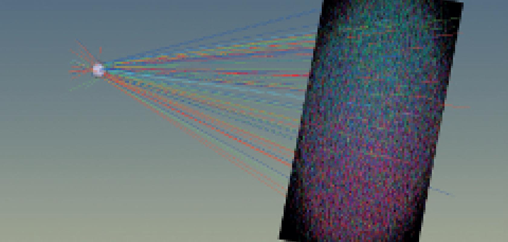
Software tools for illumination are much younger than those for imaging; illumination software was developed in the 90s, whereas Code V, for example, had its beginnings in the 1960s. The algorithms for both imaging and illumination are also seeing improvements in speed, allowing optical engineers to generate models faster. Code V’s Beam Synthesis Propagation (BSP) tool, which is a general diffraction propagation algorithm for some classes of systems – most notably laser systems and telecom optical devices, for instance – was developed as part of a NASA research project to speed up simulation time. The project looked to model telescope optics for imaging exoplanets – planets circling distant stars, between which there can be 1,011 orders of magnitude difference in brightness. The optical system would have to suppress spurious energy from diffracted light very efficiently in order to identify exoplanets. ‘While there were tools that might have allowed NASA to do this, the calculation time would have been measured in years in order to achieve the level of accuracy needed,’ comments Hasenauer. ‘The BSP algorithm was developed in response to this and cut the calculation time to weeks. This is not a typical problem and most of our customers that use BSP are getting answers in seconds or minutes.’
Computation time is still an issue for some applications. Overall, though, improvements in computing hardware, along with developments made in the optical design algorithms, are allowing optical engineers to model larger design spaces, more quickly and with greater accuracy.