Optical design in photonics is dependent on many variables, but often the overarching application will determine, to a large extent, the optical setup. An extensive array of optical components is available, varying in their mode of operation and resulting effect. Diffractive optical elements (DOEs) are one such class of optical components and include diffraction gratings and beam splitters, as well as crystalline structures, all of which operate through diffraction.
Diffraction can be described as the bending of waves around small obstacles and the spreading out of waves past small openings. The ruled diffraction grating, for instance, contains a series of structures at different heights or angles that serve as corners for the light to bend around. The principle applies to all types of wave, although, in the case of diffractive optics, light waves are manipulated.
The effects of diffraction arise due to the way waves propagate. Incident light waves impacting on a surface, such as a diffraction grating, behave as a series of infinite waves that interfere with one another, cancelling out or adding together as they become in and out of phase with one another. The interference creates specific patterns of light, which can be used in applications from metrology to 3D imaging.
Dr Andreas Hermerschmidt, senior scientist and head of the diffractive optics group at Holoeye Photonics, notes that classifying diffractive optics can be difficult, as often the same optical element might be referred to differently depending on the person. However, Hermerschmidt suggests that generally, there are at least two basic types of DOE. There are those that have a focal power and are designed to focus light at a finite distance. These are dependent on alignment of the element with the beam. Then there are those that do not need to be aligned, such as optical gratings that operate through Fraunhofer diffraction. Here, the beam simply needs to hit the DOE to achieve the desired effect.
A second potential classification is a split between surface relief elements and volume elements. DOEs can have a surface relief structure designed to diffuse light based on diffraction. This is in contrast to certain diffusers, where the material is ground and melted together without any surface structuring or Bragg gratings.
‘In principle, diffractive optics create multiple diffraction orders from one light beam,’ explains Hermerschmidt. This, incidentally, has implications for laser safety, as a laser with a fixed diffractive element won’t generate a single powerful beam harmful to human eyesight and therefore will be given a lower laser safety class. ‘The aim for many applications is to suppress certain diffraction orders while focusing others to create a light pattern,’ says Hermerschmidt. For example, one of the techniques for 3D imaging is based on patterning an object with dot arrays or stripes. Cameras capture images of how the spots are arranged over the object and image processing algorithms are used to generate a 3D model of the object.
DOEs create lines made up of a number of overlapping dots, the spacing of which will depend on the distance of the object from the light source. ‘For imaging applications requiring multiple lines, solely using diffractive optics might not be suitable,’ notes Sylvain Bosse, sales engineer at StockerYale.
StockerYale, with headquarters in Salem, New Hampshire, US, produces a lens which, when used in combination with a DOE, can create multiple, uniform, solid lines without dots. The DOE portion recreates the line generated by the lens. ‘Multiple laser lines provide more information per image than a single line, and this is beneficial for imaging using laser triangulation, capturing very fast moving objects, or where there is only one image taken of each manufactured part,’ explains Bosse.
Diffractive optics can be used to generate any number of patterns from continuous lines to crosses. Aside from 3D imaging, light patterns are used in applications such as optical metrology, whereby a cross is used to pinpoint where a measurement is to be taken or align a drill piece on the area to be machined. Other applications range from barcode scanners, allowing operators to see the area being scanned, to security applications such as face recognition, which could, in principle, be carried out using optical patterning.
A more efficient solution
Hermerschmidt notes that using diffractive optics distributes the light much more efficiently than a conventional projector. ‘To create a pattern with a low fill factor (only 100 spots, for instance) using a projector, most of the light has to be blocked from the target area. A DOE, on the other hand, will steer the light to where it’s needed, which is more light efficient.’ A DOE can also be engineered into a more compact package than a projector.
As a further example, specific beam profiles can be created using diffractive optics – it is preferable to have a flat top beam profile for laser ablation, for instance. This can be generated by expanding a Gaussian beam and cutting out a small area of light, or, alternatively, the light can be redistributed by a DOE.
According to David Henz, product line manager at Edmund Optics, a popular use of diffractive optics is in medical systems, specifically in spectroscopy, one of the reasons being the high light efficiency DOEs provide. Fluorescent spectroscopy is used in medical research to identify different proteins or in gene expression studies, and DOEs can be used to control the light dispersion rather than using a more traditional dispersive element, such as a prism. ‘By choosing to use a DOE, the end user can achieve more efficient light dispersion as well as obtain increased resolution,’ says Henz. This would allow for increased accuracy and repeatability in results.
However, one disadvantage with using diffractive optics is their relatively low tolerance to changes in some input beam parameters compared to refractive lenses. In particular, DOEs are heavily dependent on wavelength. Changes in wavelength lead to changes in the interbeam angle of beam splitters, for example, which is roughly linearly proportional to the wavelength. ‘Refractive lenses, on the other hand, can contain aberrations, but even a simple lens will operate over more or less all wavelengths,’ says Hermerschmidt.
Steffen Reichel, senior manager, business development at Schott Advanced Optics, notes that, as DOEs depend on illumination wavelengths, they are best suited to monochromatic applications that use only one light wavelength.

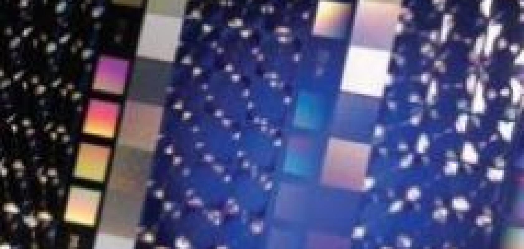
Edmund Optics’ transmission gratings are designed to disperse incident light at specific angles.
Henz says that, with regards to ruled diffraction gratings, the spacing of the grooves and the overall efficiency of the grating can impact on the optical system. A ruled diffraction grating is typically created from a master copy – a highly polished substrate coated with a thin layer of evaporated metal (gold or aluminium). A ruling engine then burnishes each groove in the coating to produce the peaks and valleys on the grating’s surface. The master is then copied numerous times.
‘The number of grooves per millimetre is important, as the longest wavelength that a grating can successfully diffract is twice the distance measured from peak to peak,’ explains Henz. Grating efficiency is also vital and is dependent on the performance of the coating and grooves.
Henz continues: ‘The light source used and the desired end result will determine the number of grooves per millimetre on the grating, while the spacing of those grooves determines which wavelength can be successfully diffracted.’
Fibre Bragg gratings
The manufacture of fibre Bragg gratings (FBGs), used as sensors in optical fibres, can be carried out through the interference patterns produced by a specific kind of DOE, called a phase mask. Fringe patterns, caused by the interference between two coherent beams, are first used to generate the phase mask consisting of surface relief patterns etched in fused silica. Phase masks splitting monochromatic light into two self-interfering outgoing beams are then used to record FBGs in the photosensitive fibre.
‘The aim when manufacturing a phase mask is to maximise the efficiency of the two beams involved,’ says Bosse of StockerYale. This is achieved by maximising the positive and negative first diffraction orders and minimising the zero order (i.e. the light that passes straight through the grating with no diffraction).
The FBG acts as a filter inside the fibre, reflecting specific wavelengths and transmitting others. FBGs are used in the telecommunications industry and also as sensors in construction projects, such as bridge building.
StockerYale’s DOEs are generated either through a lithographic process, using a master mask placed between a UV lamp and the recording substrate, or through a holographic process, i.e. using the interference pattern from two coherent beams to etch the microscopic profile onto the photosensitive material. ‘By carefully controlling the geometry of the holographic setup, we can determine precisely the period of the recorded DOE,’ says Nadia Capolla, principal optical scientist at StockerYale. The period of the phase mask will dictate the pitch of the FBG, thus ultimately regulating its wavelength filtering properties.
The method used to manufacture diffraction gratings depends on the final light pattern required. From the intended pattern, the optimal interference pattern can be calculated and the method of manufacture determined.
Computer generated holography (CGH) is a method of digitally generating holographic interference patterns. Schott Advanced Optics manufactures computer-generated holograms, which can be adopted for beam shaping and splitting, among other applications. The interference patterns can be used to generate pictures or certain beam shapes. Pico-projectors, designed to project an image onto mobile phone screens, are equipped with these optical elements to shape a Gaussian beam profile into a flat-top beam to distribute the light evenly across the screen. CGH can also be used in laser systems to split the beam or to create masks for generating holographic images.
‘One of the major advantages with using diffractive optics is that they can decrease the size of optical systems and offer new optical functionalities,’ comments Reichel of Schott Advanced Optics. ‘There is a drive towards engineering smaller optics in a number of application areas and DOEs can provide a very compact solution.’ Pico-projectors on mobile phones are one good example of the requirement for smaller optical systems.
Hermerschmidt of Holoeye Photonics comments: ‘Typically, there are a number of different ways to achieve a desired optical effect and the full set of specifications for the application should be taken into account when deciding on the suitability of using diffractive optics.’ However, he says that in some instances, DOEs can reduce cost and the level of complexity of optical setups. For example, if a customer wanted to create 20 beams from one laser beam, a number of prism beam splitters could be used to generate the effect, which would be costly and difficult to align. A single DOE could produce the same effect much more cheaply and with fewer optical elements.