Experimental error is a fact of life and it can be caused by the erroneous turn of a screw or the heating of the smallest component of an experiment’s assembly. Ensuring an optical component is rigidly in place is paramount for experiment or process success.
‘If your goal is micron-level performance or better, then having your motion system correctly designed and set up is key – and, at this level, even changes of load can dramatically alter the control loop characteristics of the system effecting the achieved result,’ says Simon Smith, European director of sales and marketing for Aerotech.
Aerotech supplies its customers with ‘motion solutions’ as Smith explains, because at this level of performance every aspect of the system can influence the results. ‘A complete motion solution is the better option to achieve the result, as our service includes understanding what is important, engineering and documenting the solution, and making sure that the manufactured system meets these requirements prior to shipment. Customers get the results they need straight from the box.’
In Smith’s experience, people think they can get a ball screw, a high-resolution linear encoder, bearings and motor and make it do what they want it to do: ‘A good percentage of people who design these systems have little idea of how the system works and fail to achieve their desired result. In today’s market, where there is a focus on generating smaller and smaller artefacts with a laser, getting it wrong can be a costly business.’
Aerotech designs systems from the ground up with high pre-load bearings and direct-drive technology, and makes sure that any resonance of the stage is well above the area of interest. This means a better servo-loop performance, and better dynamic tracking for the solution. For Smith, when designing a motion system it is the harmony of all the components in the system, including the control loop, that must be considered.
‘When you have a system where you are trying to have a high-performance micron or sub-micron-level system, the amount of resolution required for the controller is typically high. Because of this, the control loop sees disturbances from external sources and the resonances from within the system – such as when the load vibrates at a natural frequency. The control loop has to be set up to know how to respond to these frequencies,’ explains Smith. An example Smith gives is getting a controller set up based on on a system with two stages XY, X on top and Y underneath X.
‘When trying to machine small circles with a laser using a combination of XY motion you need to make sure the bandwidth of the two stages is balanced. As the bottom axis is carrying the top axis, it is important that the stages are tuned for the application. If not, and the speed increases, you can end up with an egg shape and not the programmed circle. We manufacture the controls we use, and the tools included are significant in getting the desired performance,’ says Smith. He also warns that, if a user has a bottom stage with five microns accuracy, by the time other stages have been added you may have 10 to 20microns of accuracy because of the compound effect.
‘We can overcome the effects of the repeatable A bbe errors by calibrating the system at the point of interest. This is done in Aerotech’s metrology facility, using laser interferometers to measure the errors, and then these are added into a calibration table to achieve the highest level of performance.’
Edmund Optics’ solution is a precise and rigid alignment system called the Techspec Cage System. ‘It is like an adult K’nex set made up of a bunch of plates and rods. The rods really make for precision alignment systems,’ says Katie Schwertz, an optomechanical design engineer at the company’s Tuscon, Arizona-based design centre. As well as demonstrating the system at trade shows, Edmund also offers the components on its website. Schwertz explains: ‘After trade shows we get a lot of calls about the applications [we demonstrated] and people ask for components for that.’
Applications include interferometry. Stephan Briggs, who works in Edmund’s product line management group in New Jersey, says: ‘They can be troubling to align in a lab, so the cage system [of rods and plates] allows perfect centricity and alignment. It allows you to build it on the fly, with repeatability.’ Another use for the cage system is an autocollimator. Briggs explains: ‘It is not as finicky as an interferometer, but it is very useful – it is modular and customisable and usually the price is 25 to 50 per cent less than a comparable system.’
Rather than an ‘out of the box’ system, Edmund’s cage system can be customised. As Briggs explains, ‘We have this complete system, but it’s not a single sellable kit. We have a BOM available and it is very rare people need exactly what we have on display, so we can tailor it.’
Beyond customisation, Edmund has developed a more complex system and used it for the company’s modular fluorescent microscopes. Briggs says: ‘We have multiple objectives with multiple light sources. It is based on confocal principles, and we are able to switch filters to change light sources. You could easily change the magnification power with a mechanical turret.’
Other advantages the cage system has, according to Schwertz and Briggs, is that – because all of the optical elements are wide open – users can see the path and the filtering, and it’s cost-effective. ‘The price of an EO cage system fluorescence microscope is typically around $10,000; the laser and objectives account for 75 per cent of the investment. This makes the optics and optomechanics affordable for a customised system’.
Southampton-based Redlux is a user of positioning systems. The non-contact nano-precision metrology company’s chief executive officer Christian Maul weighs up various factors when thinking about positioning systems. ‘One of the starting questions was whether to buy something that was fully ready, or have a more DIY approach to these systems,’ he says. ‘There is a trade-off to be made; you need to spend a lot of time to get it working, buy something off the shelf, or get a system integrator to build something.’
For Maul, positioning systems used for movements from millimetres to 50 micrometres ‘tend to be straightforward’ and this is reflected in the price. ‘You can buy positioning systems complete with everything you need for £1,000 per axis, maybe £500 pounds per axis.’ But, Maul points to significant differences as the micrometre increment diminishes to the nano: ‘When you go below 20 micrometers to the one-micrometer to nanometre range, these things don’t behave the way you expect them to behave because of temperature effects.’
With such challenges, Maul’s view is that to develop such a system to achieve even micrometre positioning is very difficult: ‘At that level I would buy something that is ready-made because the complexity of getting a positioning system to do what you want it to do grows exponentially, the higher the resolution or accuracy you want.’ For Maul, it is just not worth developing such a system for a one-off if you can buy something that is integrated by ‘someone that does it all the time’.
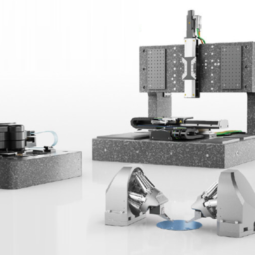
Kevin Grimley, managing director of Physik Instrumente in the UK, is running a business that is all about resolution accuracy. ‘A lot of the development work we do is in response to new demands and a lot of our work is focused on the semiconductor market,’ says Grimley, whose company is based at Cranfield Technology Park. ‘There is a constant drive to reduce line width. They are hitting nodes of 30nm and there is focus on extreme UV (EUV) based systems to try and reduce that line width even further.’ The solutions PI is providing often deal with moving an optic or a manufacturing machine, or a sample or a wafer underneath the light source. With the focus on EUV putting much higher demands on equipment to align the elements inside the lithography machine, there is also a requirement to make sure the wafer is aligned also.
Grimley says: ‘These demands are pushing us and our technology forward in terms of the type of drives that are applied in those application – but it has also required us to look at a lot more detail at the metrology side of it.’ Grimley’s engineers know that, for positioning systems for the highest demanding applications, users need to be able to operate, reliably, some form of closed-loop operation. ‘You normally have a mechanical drive, a motor of some form, and there are motors out there – stepper motors – that can give you a predetermined step of motion for every increment of the motor itself.’ However, Grimley warns: ‘If you want to reliably know where you are in terms of repeatability of position, if you want to ensure you’re not missing any position information, you need some form of positioning metrology built into a stage.’ He points to a problem with stepper motors: they can miscount, and in their market research Grimley’s engineers find few systems capable enough for challenges like EUV. Finally Grimley’s team just had to do it themselves: ‘We had to develop our own metrology or work with groups out there that are developing state-of-the-art forms of metrology.
‘We had to try and ensure that we can get the most out of the motor and mechanical and control technologies.’
The experiences of Aerotech, Edmund, PI and Redlux show the challenges photonics continues to present, while offering the potential of great advances for industries that decide to deploy light technologies to improve their products.


