From smartphone cameras and displays to the parking sensors in your new car, optical systems are being integrated into an increasingly diverse range of applications. Virtual and augmented reality headsets and OLED displays are just a couple of examples of where the photonics industry is not just entering new markets, but working at the cutting edge of them.
How can the optical industry design and test the sheer range of optical technologies that are in such demand?
The simulation and computer-based design of optical systems could help match this demand because it significantly reduces development costs and times, according to Petra Wyrowski, chief marketing officer at LightTrans International, who said: ‘Accurate system modelling reduces the number of failed prototypes and helps to identify the critical parameter in the system.’
Valerio Marra, marketing director at Comsol, added: ‘Design mistakes can be corrected very early on in the process and thousands of ideas can be tested virtually before the first physical prototype is built. The overarching benefit of numerical simulation is a shorter time to market and less unexpected downstream costs.’
Optical simulations also allow researchers to model the propagation of light in a range of systems. Dr Jake Jacobsen, technical marketing manager at Synopsys, explained: ‘One of the key benefits, beyond design and layout aspects, is that optical modelling software gives the designer a set of tools to really understand the way that light is propagating through the system. A variety of tools are available in our software to analyse how light is traversing the system in question. This gives the user the ability to quickly identify, diagnose and resolve issues before building the hardware.’
Application areas
There are many applications that can be improved with the use of optical modelling software. David Hasenauer, Code V product manager at Synopsys, said: ‘The three [application areas] showing the highest growth are automotive optics (including non-imaging systems), optics for smart devices such as mobile phones and tablets, and wearable devices for virtual or augmented reality.’
Jacobsen added: ‘For the illumination market, some of the biggest applications are general lighting, that is, the design of luminaires and other fixtures and light distribution devices; automotive lighting for both exterior and interior lighting; information display including backlit displays and the design of LED packaging.
‘For our imaging software, there is high demand for personal imaging and display devices such as mobile cameras, wearable displays as well as head-up displays.
‘We also see continuing usage in our more traditional markets of lithography, remote sensing, scientific instruments, microscopy and a wide variety of other applications where image quality is paramount,’ he added.
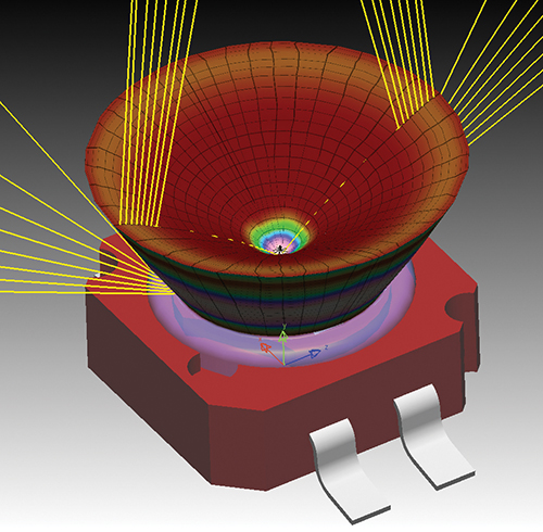
LED optics designed in Synopsys LightTools software with illuminance visualisation in the 3D Design view
While traditional application areas – such as aerospace, medical, and security cameras – are still going strong, thanks to the maturity of these technologies and their cost-effectiveness, optical software suppliers are also experiencing growth for emerging technologies, such as organic light emitting diodes (OLEDs).
OLED technology
OLEDs are popular because they can be integrated into lightweight, paper-thin, light-emitting panels in a variety of shapes and sizes. Unlike their LED counterparts, they can be used to create flexible or bendable lighting devices applied to a flat or curved surface area. But OLEDs aren’t nearly as bright or as energy-efficient as LEDs, so researchers are racing to develop new designs.
Scientists at Konica Minolta recently used Comsol Multiphysics to model surface plasmons. The objective was to design nanostructured electrodes that show promise for increased light output and efficiency in OLED systems.
Light losses in an OLED can occur through several mechanisms, such as differences in the refractive indices of each layer that can cause light to reflect within the layers, rather than travelling outward. Another mode of loss is through the decay of surface plasmons – waves of oscillating electrons on the surface of a conductor – which was investigated by the team at Konica Minolta. Marra said: ‘Here Comsol Multiphysics electromagnetic modelling capabilities are used to analyse ways to prevent light loss by means of a nanograting structure. Through their simulations, the team determined that they could reduce the plasmon losses by 50 per cent using the optimised nanostructure surface for the cathode.’
Small scales
Optical modelling at small spatial scales is necessary but difficult, as Jacobsen explained: ‘Our products also address the propagation of light in very small spatial scales where ray tracing is inadequate and the software must solve Maxwell’s equations directly to get a good solution. These simulations are often related to optical networking devices and patterned nanostructures on LED chips to enhance light extraction and thus efficiency, among many other applications.’ Such applications include the use of quantum dots in display technology, as well as other fields.
Jacobsen added: ‘OLEDs themselves can be modelled in Synopsys LightTools software as a source (or as a full display), but most of the interesting modelling goes on at a spatial scale, where ray tracing is not effective.’
For this kind of modelling, you can use Synopsys RSoft tools to generate the output light that can then be fed as a ray data source into its LightTools illumination design software, according to Jacobsen. RSoft and LightTools software support this interaction with a set of standard tools. The same is true when modelling an LED chip itself (for the same reasons).
As for quantum dots, the LightTools phosphor model can support the modelling of quantum dots provided that the dots themselves can be characterised. Jacobsen added: ‘The performance of individual dots themselves are too small for LightTools to simulate and in any case, the operative physics is not addressed by LightTools’ ray tracing capability.’
This is a fundamental challenge for optical modelling software: when a given technology pushes the boundaries of the physics that define a particular space. For instance, with small extraction features for backlit displays or LED packages, when the feature size gets too small for ray tracing to effectively model, then another approach must be used. Jacobsen said: ‘For this we have developed an interface between our RSoft photonic device design tools and LightTools. The small features can be modelled using RSoft tools, which then produces a data file that can be used as a measured BSDF file in LightTools.’
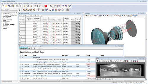
Automotive backup camera design and image simulation in Synopsys Code V optical design software
The software industry must keep pace with the demands of the photonics sector to simulate such emerging technologies, Jacobsen added: ‘We monitor emerging technologies that may be of interest to our customers. We then evaluate if an emerging technology can be addressed with our current set of optical modelling tools, or if modifications or additional capabilities are needed.
Optimisation matters
For illumination engineers, a large challenge is just in the optimisation itself. Imaging optimisation, while absolutely critical, is usually a very narrowly defined problem. The light goes through a set of surfaces in a particular order to a final surface where the user is usually interested in getting as good an image as possible. This narrow problem definition leads to a more tractable problem than you encounter in illumination design.
In illumination design, the light does not follow a predefined path and the target state can be any number of things, from a simple alignment problem or uniform illumination, to a particular angular intensity pattern, such as what is found in the design of low-beam headlamp design.
Jacobsen said: ‘But without an effective optimisation capability, the designer is really relying on experience, trial and error, and to some extent, blind luck. It’s not a terribly efficient process.
‘For the illumination engineer, another one of the biggest challenges is the accurate assignment of optical and material properties. Users must model correctly the way that light will interact with a given surface or scattering material. Without accurate data, the model results are just estimations at best.’
Optical modelling and optimisation algorithms also need to be flexible to adapt to the varying optical systems. Different types of optical systems require a different level of simulation accuracy and different physical effects need to be taken into account. Wyrowski said: ‘For instance, the simulation of an image generation unit that is based on a scanned coherent laser beam needs to take into account the coherence and beam diffraction of the laser light, whereas in an image generation unit that is based on a conventional incoherent light source, these effects might be neglected.’
‘VirtualLab Fusion allows for the adjustment of the simulation accuracy on the specific simulation task. As an example of this versatility, VirtualLab Fusion comes with both a ray – and a field-tracing engine, thus giving the optics designer a great flexibility in setting up the optical simulations,’ Wyrowski added.
Environmental Factors
Optical systems must also demonstrate flexibility for the ways in which they could be used. For example, Cypress Semiconductor recently used multiphysics simulation to optimise a touchscreen design for use in a diverse range of products including smartphones, laptops, automotive and industrial devices, and home appliances.
The objective was for the touchscreen to respond flawlessly under a variety of conditions – for example to give the same response regardless of the user’s finger size, whether or not they have recently applied hand cream, or whether the phone is resting on a flat surface or in a pair of hands. Marra said: ‘Here, Comsol Multiphysics electrostatic modelling capabilities are used to optimise the design of capacitive touchscreens consisting of varying layers of transparent lenses, substrates, adhesives, and indium-tin-oxide (ITO) electrodes.’
Design parameters were varied, including the number and geometry of layers, materials, and special boundary conditions, such as floating potential. In order to extend the usability of their models and communicate more effectively with their customer support teams, Cypress engineers used the Application Builder in Comsol Multiphysics to create simulation apps based on their models.
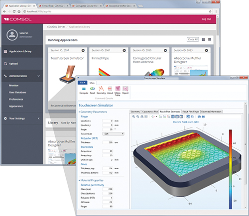
Using a local installation of COMSOL server, design teams can give colleagues and customers worldwide access to their simulation apps through a web browser
Marra explained: ‘Before they started using simulation apps, any time a customer wanted a design that was slightly outside of their design box, R&D engineers would have to be involved again to run simulations for minor parameter changes. A lot of times, a sales engineer might try to run the simulations themselves, even though they had little experience using the Comsol software. Additionally, R&D engineers would have to check the simulations, as their colleagues run the simulations – this takes more seats on the software, which could prevent other engineers from running their simulation.’
Cypress engineers decided to build simplified user interfaces over their models, i.e. custom simulation applications, for their colleagues and customers to be deployed via Comsol Server license. One of the apps they created lets the user change design parameters ranging from finger location to thickness of the different layers in the sensor. The app generates a report detailing the capacitance matrix, an integral piece of information for capacitive sensor design. It can also show the electric field distribution in the sensor and a drop-down list can be used to select a solution corresponding to the excitation of different sensor traces.
Marra said: ‘One of the biggest challenges is the combination of requirements from reliability, safety, aesthetics/looks, ergonomic design, time-to-market, and environmental aspects. All of which frequently pulls the design in different directions. The use of multiphysics software… allows engineers to consider all of these requirements in one go and increase the probability of successfully meeting deadlines.’
Lost in translation
Two further challenges for optical modelling software are the import of measured physical data into a format the optical program will understand, and comparing the difference between software simulation and hardware measured results.
Michael Gauvin, vice president of sales and marketing at Lambda Research, said: ‘[Our] software addresses these challenges by using utilities to help users import measured source and surface scatter data quickly. Using the digitisation capabilities inherent in TracePro, for instance, users can digitise screen-captured spectral and angular radiation distributions from the LED manufacturer’s data sheets or BSDF data. In terms of comparing measurement and simulation, this is a constant learning process where surface and source data needs to be correctly simulated in the software, or the results will be incorrect, in some cases by orders of magnitude.’
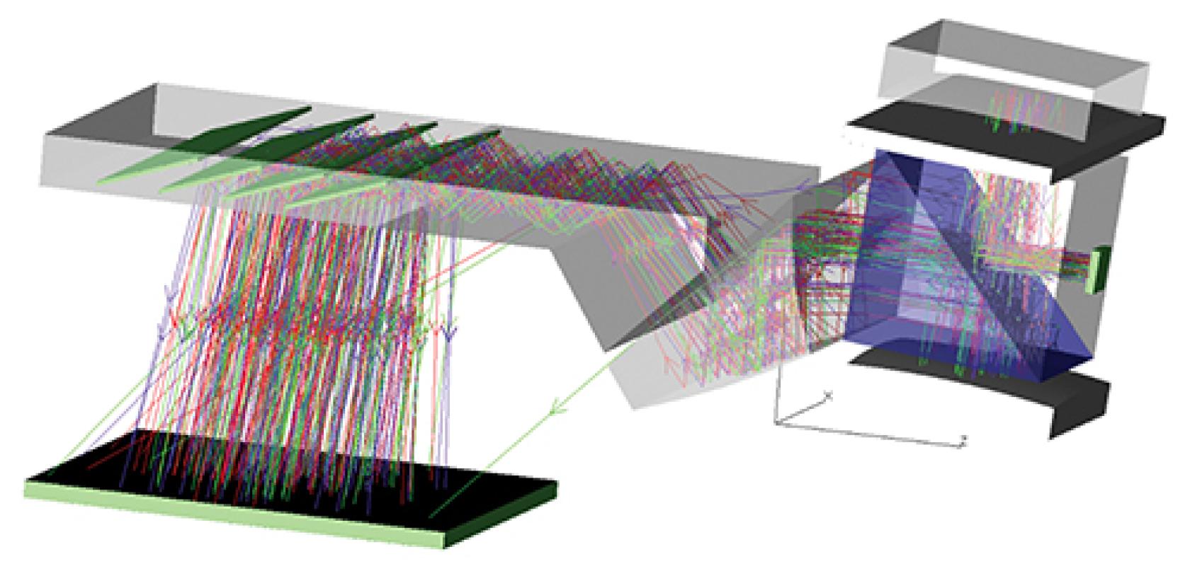
TracePro is a 3D CAD virtual prototyping system. Optical engineers who want to model the complete optical train can import the CAD model from a CAD program or build it inside TracePro’s CAD kernel. Users then add optical properties, setup sources and then raytrace the system for further analysis and design. ‘The 3D visualisation of how rays propagate to any surface and the display of power going through the system is the most important aspect of virtual prototyping software. It lets the user understand how their system is working optically before manufacture,’ Gauvin added.
User understanding is a final, important factor for optical modelling software. Simulation tools provided by Comsol, for example, promote collaboration across departments, which has an important impact on design teams and their workflows. Marra explained: ‘Our multiphysics technology enables the same workflow across departments covering widely varying areas, such as electromagnetics, structural, acoustics, heat transfer, fluid flow, and chemical engineering. In addition, simulation apps created with the Application Builder and deployed with Comsol Server allow departments such as manufacturing, sales, and even marketing, to test the effect of a new product requirement before initiating a design iteration – freeing the design team from repetitive tasks performed on previously validated numerical models.’
‘While a simulation app relies on a detailed model and complex calculations happening behind the scenes, the app user doesn’t need to be an expert in the software or in the physics involved,’ he added.
Usability will be the key to truly unlocking the world of simulation to the optical industry. As more applications, environments and innovations hit the market, a broader range of users must be able to use optical modelling software to keep the photonics industry innovating and its devices improving.