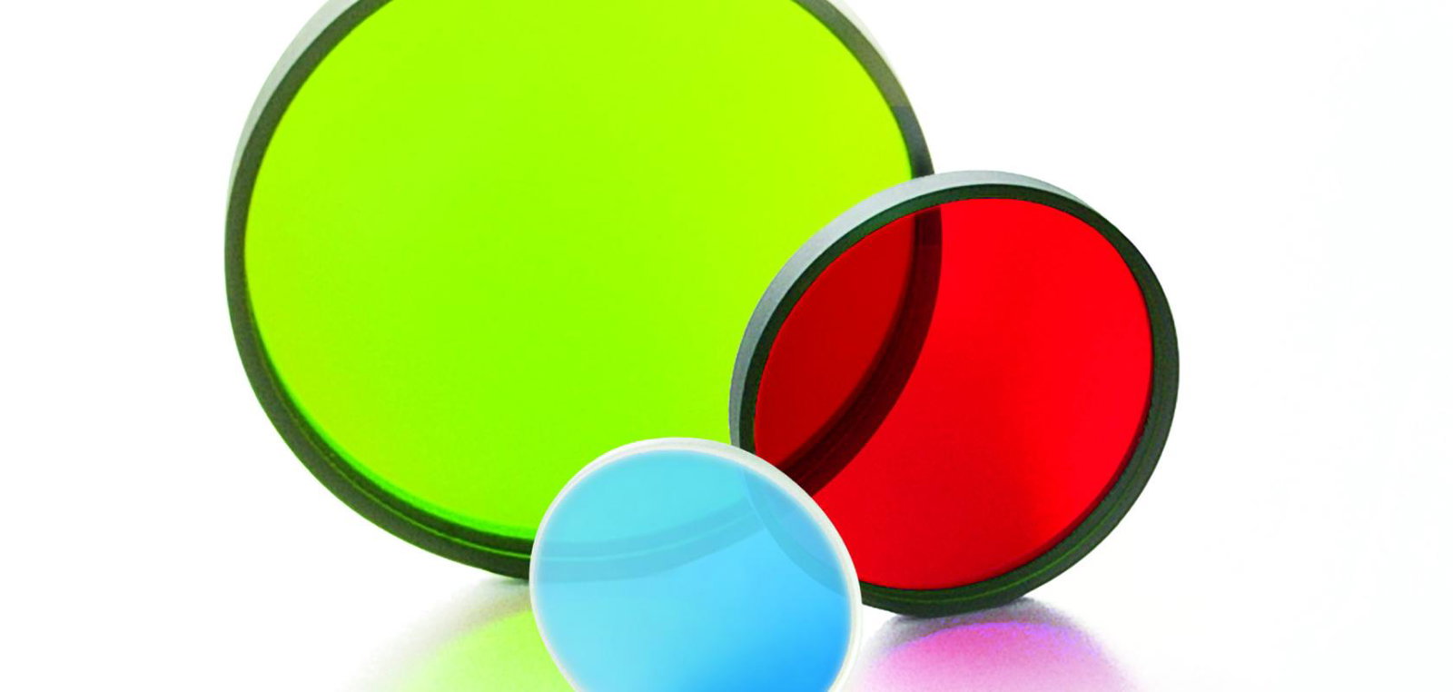
John Atkinson, Principal Engineer at Chroma Technology, explains why engineers so often confuse angle of incidence with cone angle, and why understanding the difference early can make or break an optical filter's performance.
In a recent article, my colleague Iain Tweedy flagged cone angle as one of the biggest challenges in machine vision, and promised more on the subject from Chroma Technology. As the engineer who fields most of those questions, I was happy to oblige.
There is one question I find myself asking customers almost every week. A request arrives with a set of angles, perhaps 0 to 20 degrees, and I have to write back: is that a cone, or is the filter simply tilted in a collimated beam? Which is it?
It sounds like a small distinction. To an optical filter, it is the difference between a predictable shift that can be designed around and a blurred, softened spectrum that is baked into the instrument.
A cone is not a tilt
Angle of incidence describes the angle between a beam and the perpendicular to the filter surface. At normal incidence, light passes straight through, and dichroics or mirrors that fold an optical path commonly sit at 45 degrees. If the beam is collimated, every ray is parallel, so every ray meets the coating at exactly the same angle. Think of it almost like a laser pointer.
What angle of incidence does not describe is the shape of the beam. Light spreads out from an LED, a lens gathers it to a focus, or a laser can be expanded. In each case, the rays trace out a cone, and the filter sees a whole range of angles at once. A cone is, in effect, a multitude of angles of incidence arriving together.
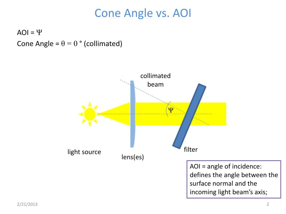
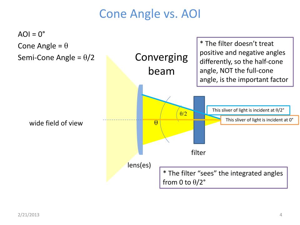
The confusion is understandable, because real systems often have both: a converging cone passing through a filter that is also tilted.
What the coating really sees
An interference filter is a stack of very thin layers, and its behaviour depends on the path light takes through them. That path is the same whether a ray tilts 30 degrees to the left of normal or 30 degrees to the right. The coating is isotropic: it responds to the size of the angle, not its direction. That is why the half-cone angle, from the central ray to the outermost ray, is the number that governs performance, not the full cone.
As the angle grows, the spectrum shifts towards the blue. In a collimated beam with a tilted filter, that shift is predictable. The shape of the band is largely preserved, with steep edges and high transmission, although at higher angles the two polarisation states begin to part company.
In a cone, every ray shifts by a different amount, and the light leaving the filter is the sum of all those slightly shifted spectra. The result is a blue shift and a softening of the edges, to a degree that depends on how the rays are distributed. There is a practical difference, too. A tilted filter can be realigned. A cone is a property of the optical path itself, so once the instrument is built, its effects cannot be undone.
Where cones come from
A cone angle is rarely something a designer chooses. It is simply a condition of the optical system. Any vision system that sees more than what is directly ahead, from the camera in your phone to the human eye, is accepting a cone of light.
Some systems sidestep the issue. Microscope objectives deliver carefully collimated beams, which is why even wide-field fluorescence microscopy is not really a cone angle problem at the filter. Lasers are collimated by nature unless a lens intervenes.
Cones become significant when space is tight and the collimating lens is the first thing to go. That is increasingly common in endoscopy, where probes must be small and use fast optics; in handheld Raman and point-of-care devices, including home diagnostics that people want tucked discreetly on a bathroom shelf; in machine vision and inspection; and in LIDAR for autonomous vehicles, where a wide field of view lets the system keep pace with fast-moving scenes. Astronomy, too, has its share of fast optics.
The price of going compact
Removing collimation makes an instrument smaller. The trade-off is that the filter has to be more highly engineered to compensate, and balancing those two pressures is a large part of my job.
How much it costs depends on the filter. A wide bandpass or edge filter can often accept a broad cone with negligible degradation, and an off-the-shelf part may do the job perfectly well. A narrow band filter is a different story. If you need a single line transmitted, any shift or blurring matters, and you are almost certainly looking at a custom design. One of our most effective tools is a coating with a higher effective refractive index, which shifts less with angle.
Is angular sensitivity becoming a bigger constraint? It is and it isn't. In satellite communications and quantum computing, we are working with large optics and beautifully collimated beams. Elsewhere, from handheld instruments to phones carrying three or four cameras, light is being squeezed into ever-smaller footprints. That is challenging, but we have been able to innovate alongside it.
We are also continually researching ways to reduce filter shift beyond what is currently possible. Some of these approaches take considerable development. But if typical solutions cannot deliver what you need, or your requirement seems to defy the bounds of physics, it is worth talking to us about what more extraordinary methods might be available.
Twenty-five designs and a better beam path
My favourite kind of customer is one who is just starting out. They are still dreaming up the instrument, they know they will need a filter, and they come to us early. At that stage, we can ask the useful questions. Do you need a lens here? Could the filter sit there instead, in collimated space, where it would be smaller, cheaper, and easier to make?
The opposite is the customer who has designed everything, cut the metal, and ordered the optics, and then calls for a filter that has to work by magic.
A recent LIDAR project shows what early engagement makes possible. The customer was developing a module for autonomous vehicles, and because the design was still open, we had room to explore. I produced around 25 filter designs, varying bandwidth, band placement, and materials, and showed how each one behaved at different cone angles and angle of incidence shifts. With those options in hand, the customer reworked the optical layout and beam path, including where the lenses would go. It took several months of back and forth to converge on a solution, and as far as I know, it works great.
That is the part of the job I enjoy most. I get a little giddy when a customer calls with a project that is challenging but, intuitively, I can see we have a solution. Then it is a matter of steering them towards it, and sometimes being straight with them: that won't work, or it will, but it will cost you far more than it needs to.
Four questions before a quote
It is surprising how often a request arrives without the basics. A filter always sits somewhere between a light source and a detector, so these are the first things I need to know:
- What is the light source? A laser, an LED, the sun, or a star.
- What is the detector? A camera, a sensor, or the human eye.
- Where does the filter sit? Near the detector, near the source, or somewhere in between.
- What must it block? It is a filter, after all.
With those answers and some knowledge of the application, I can usually work out the best place for the filter and what effect a cone or a tilt will have.
This matters because cone angle problems are hard to diagnose after the fact. Most customers do not have a spectrophotometer, and the easy-to-use ones introduce a cone of their own and give the wrong answer. What engineers see instead is background noise, lost contrast, or a general decline in image quality with no obvious cause. Without the spectral data, it is very difficult to pin down. With the beam path understood up front, we can predict those problems and head them off.
The message for designers
If there is one thing I would like every engineer to take away, it is this: know whether your filter sees a tilted beam or a cone. The beam path is one of the very first questions that needs answering before I can begin a design.
Other advice includes:
- Specify the half-cone angle: It is the half-angle, not the full cone, that governs how the filter performs.
- Match the filter to the cone: Wide band and edge filters tolerate broad cones well; narrow band filters in fast optics usually need custom engineering.
- Weigh the lens you remove: Dropping collimation saves space but moves the burden onto the filter, with consequences for performance and cost.
- Talk to us before you finalise: You do not need every specification worked out. It generally works better when we solve it together.
At Chroma Technology, you can get straight through to an engineer without jumping through hoops. Speaking to an actual human about your optical path may feel like a novel concept, but it is often the quickest route to a filter that does exactly what you need.